Photoelectric-integrated mechanical shaft keyboard switch module
A keyboard switch, photoelectric switch technology, applied in electronic switches, electrical components, pulse technology and other directions, can solve the problems of low photoelectric coupling efficiency, single touch of optical axis keyboard keys, cumbersome production operation procedures, etc., to meet the requirements of high frequency and long time. The application of time, the effect of improving production efficiency and quality stability, and reducing labor and welding costs
- Summary
- Abstract
- Description
- Claims
- Application Information
AI Technical Summary
Problems solved by technology
Method used
Image
Examples
Embodiment 1
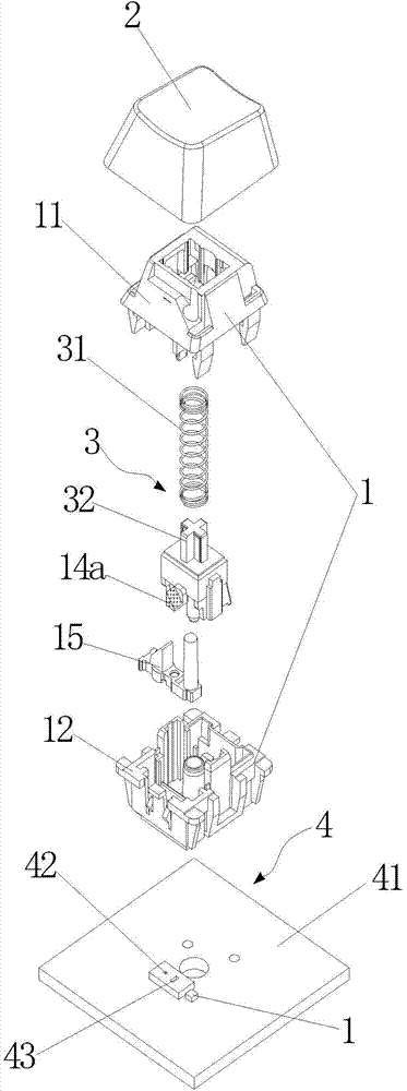
[0035] Please refer to Figure 3-7 , the figure shows a photoelectric integrated mechanical axis keyboard switch module, including a housing 1, the housing 1 is composed of an upper housing 11 and a lower housing 12, and the key cap installed on the upper part of the housing 1 2. Characters are engraved on the upper surface of the key cap 2, and it also includes a driving device 3 installed in the housing 1, a photoelectric switch 4, a moving optical assembly 14a and a fixed optical assembly 15, and the moving optical assembly 14a is installed in the driving On the device 3, the photoelectric switch 4 includes a PCB board 41, an SMDIR tube 42 integrated on the PCB board 41, the SMDIR tube is a surface-mounted infrared diode, and an SMDPT tube 43, and the SMDPT tube is a surface-mounted photoelectric diode. The sensor controls the relative position of the movable optical assembly 14a and the fixed optical assembly 15 by pressing the key cap 2 to make the driving device 3 drive ...
Embodiment 2
[0043] Such as Figure 8 As shown, the fixed optical component 15 is a prism 25 with a collimating and turning prism structure, which is composed of a plane 251 , an aspheric lens 253 and a total reflection slope 252 . In this embodiment, the moving optical assembly 14a and the key cap character illumination light guide system 6 for illuminating the characters on the surface of the key cap 2 are the same as those in the first embodiment. The fixed optical assembly 15 has a different design. The Fresnel lens 151 originally used for collimation is changed to a plane 251, the first plane mirror 153 is changed to an aspheric lens 253 for collimation, and the total reflection slope 252 is the same as in Embodiment 1. ,constant. Since the processing of the aspheric surface is easier than the processing of the Fresnel lens, and the precision requirements for the processing tool are lower, the second embodiment can reduce the requirements for the processing technology, thereby reduci...
Embodiment 3
[0045] Such as Figure 9 As shown, the fixed optical assembly 15 is a prism 35 of a collimating and deflecting prism structure. In this embodiment, the moving optical assembly 14a and the key cap character illumination for illuminating the characters on the surface of the key cap 2 The light guide system 6 is the same as the first embodiment. The fixed optical assembly 15 has different designs. The light incident surface 351 of the prism 35 is a plane, which does not collimate the light incident from the SMDIR tube, and the total reflection surface 352 is asymmetrically free in the inclined X and Y directions. A curved surface, which is an off-axis quadratic surface or a double taper coefficient curved surface, plays the role of turning the light path and collimating at the same time, and all the light rays that are totally reflected by the free curved surface 352 are parallel to the direction perpendicular to the vertical plane 353 shoot out. When the moving component 14a i...
PUM
 Abstract
Description
Claims
Application Information
 - R&D
- Intellectual Property
- Life Sciences
- Materials
- Tech Scout
- Unparalleled Data Quality
- Higher Quality Content
- 60% Fewer Hallucinations
Browse by: Latest US Patents, China's latest patents, Technical Efficacy Thesaurus, Application Domain, Technology Topic, Popular Technical Reports.
© 2025 PatSnap. All rights reserved.Legal|Privacy policy|Modern Slavery Act Transparency Statement|Sitemap|About US| Contact US: help@patsnap.com


