
Linear, inductance based control of regulated electrical properties in a switch mode power supply of a thermal processing system

a technology of inductance and switch mode power supply, which is applied in the direction of adaptive control, electric/magnetic/electromagnetic heating, instruments, etc., can solve the problems of limited minimum and maximum load, difficult to constrain and often inability to control the operation of the power supply within a linear control range using known linear control techniques, etc. smps design can be facilitated, load restrictions removed, and the effect of saving

Active Publication Date: 2008-04-10
HYPERTHERM INC
View PDF22 Cites 37 Cited by
  • Summary
  • Abstract
  • Description
  • Claims
  • Application Information

AI Technical Summary

Benefits of technology

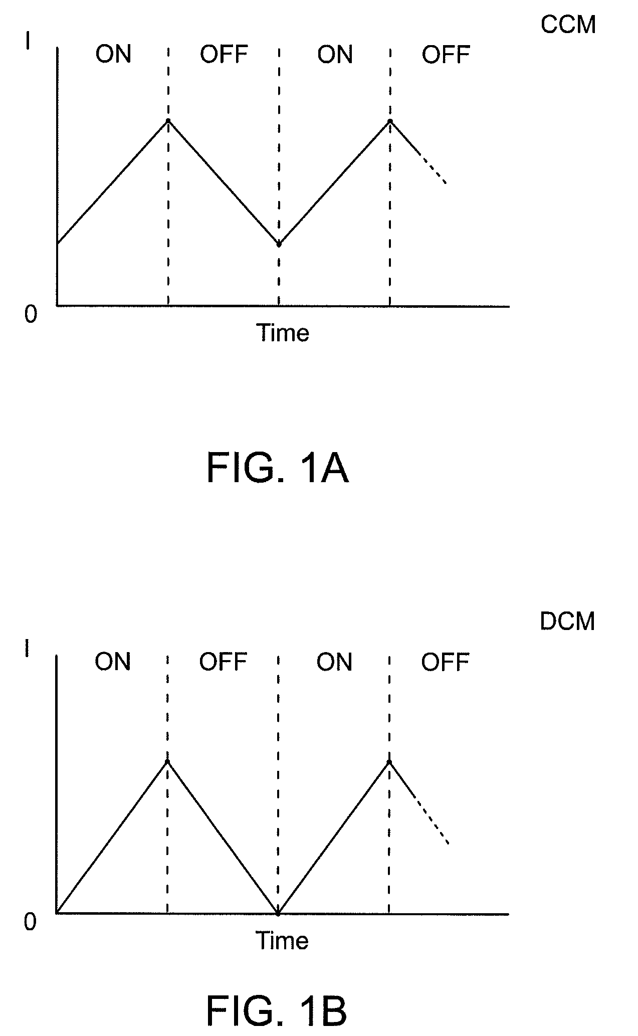
[0011]It is desirable to have a control method for a switch mode power supply that is in fact linear, such that a selected voltage or current can be achieved regardless of variations in electrical inputs and outputs of the switch mode power supply or operation in DCM, CCM and transitions therebetween. As a result, removal of load restrictions and more economical and efficient SMPS designs can be facilitated.

Problems solved by technology

However, in other applications, such as those involving thermal processing systems, it is very difficult to constrain operation of the power supply within a linear control range because the load and load processing varies over time.
As a result, attempts to control operation of the power supply within a linear control range using known linear control techniques is often not possible.
Such restriction can lead to limitations in terms of minimum and maximum load and also limitations on the design of the element(s) of the SMPS.

Method used


Image

  • Linear, inductance based control of regulated electrical properties in a switch mode power supply of a thermal processing system
  • Linear, inductance based control of regulated electrical properties in a switch mode power supply of a thermal processing system
  • Linear, inductance based control of regulated electrical properties in a switch mode power supply of a thermal processing system

Examples


Embodiment Construction

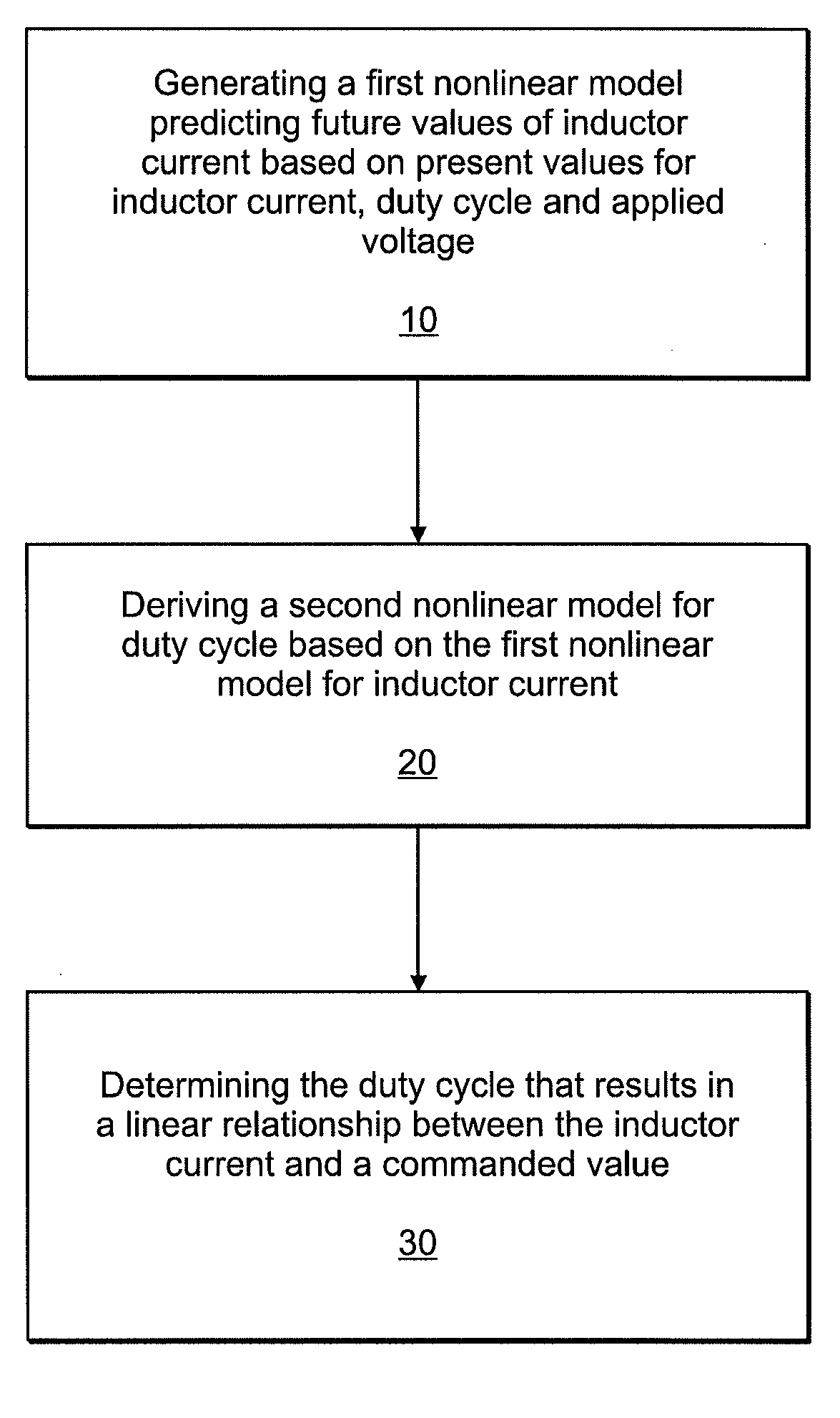
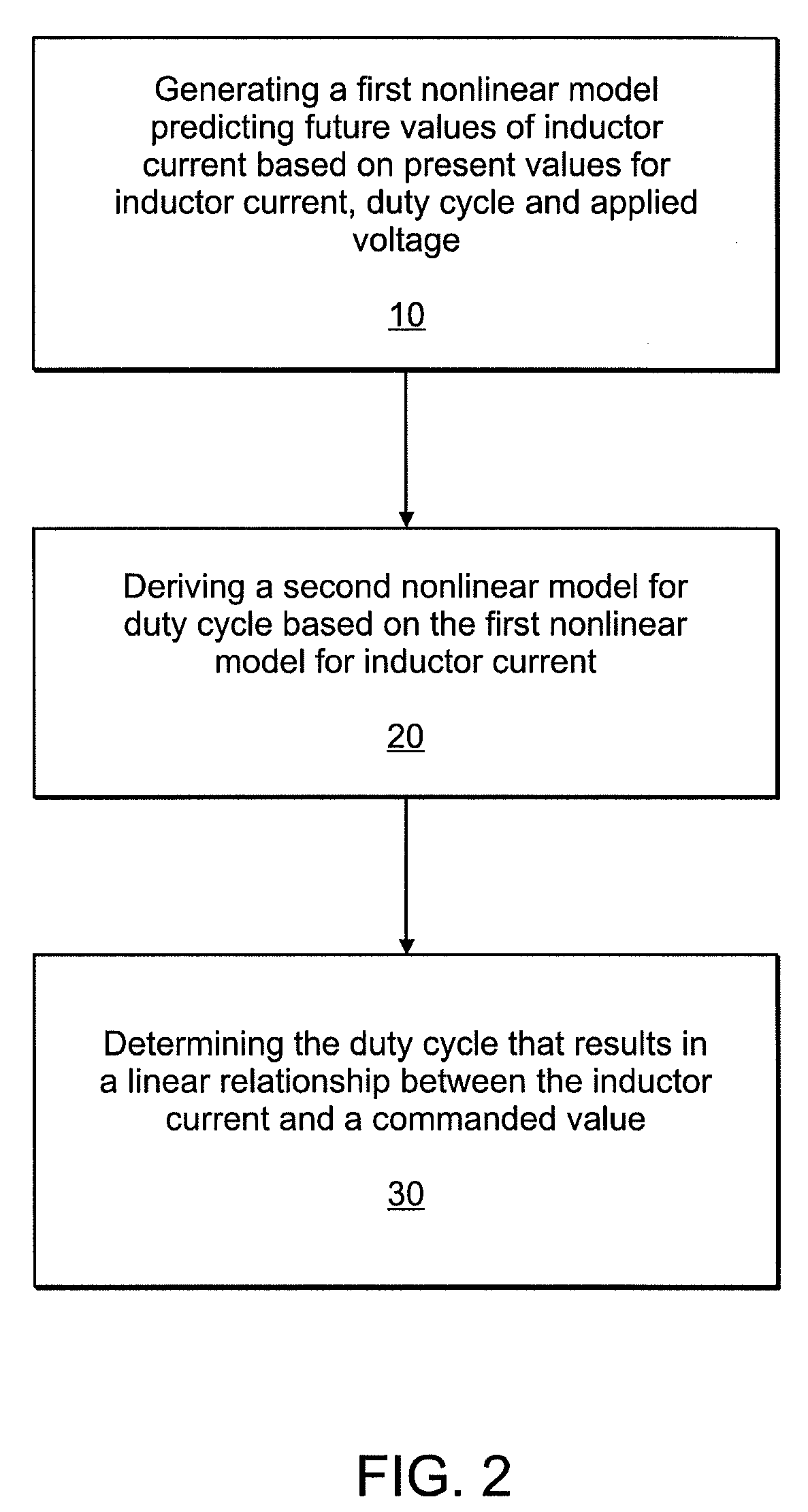
[0030]According to one aspect, a method and apparatus is featured for providing linear control of a regulated electrical property (e.g., current or voltage) in a switch mode power supply of a thermal processing system that includes an inductive element and at least one switch. The method and apparatus feature structure, or steps, for generating a nonlinear model that predict values for a regulated electrical property of the inductive element in the switch mode power supply of a thermal processing system based on a given duty cycle of the at least one switch and structure, or steps, for generating a nonlinear model that determines a duty cycle for the at least one switch based on the nonlinear predictive model for the regulated electrical property, the nonlinear model determining the duty cycle such that a linear relationship results between the regulated electrical property and a selected value.

[0031]The method and apparatus can also include further structure, or steps, for determin...


PUM


Abstract

A method and apparatus is featured for providing linear control of a regulated electrical property (e.g., current or voltage) in a switch mode power supply of a thermal processing system that includes an inductive element and at least one switching element. The method and apparatus feature structure, or steps, for generating a nonlinear model that predict values for a regulated electrical property of the inductive element based on a given duty cycle of the at least one switching element and structure, or steps, for generating a nonlinear model that determines a duty cycle for the at least one switching element based on the nonlinear predictive model for the regulated electrical property, the nonlinear model determining the duty cycle such that a linear relationship results between the regulated electrical property and a selected value. A method and apparatus is also featured for providing cross regulation between pre-regulator and post-regulator power stages of a switch mode power supply of a thermal processing system.

Description

RELATED APPLICATION(S)[0001]This application claims the benefit of U.S. Provisional Application No. 60 / 825,544, filed on Sep. 13, 2006. The entire teachings of the above application are incorporated herein by reference.[0002]This application relates to co-pending U.S. patent application Ser. No. ______ , (Attorney Docket No. HYP-083) entitled “Arc Voltage Estimation And Use Of Arc Voltage Estimation In Thermal Processing Systems,” filed concurrently herewith. The entire teachings of the above application are incorporated herein by reference.BACKGROUND[0003]A Switch Mode Power Supply (SMPS) is a broad category of power supplies that are useful for applications requiring substantial amounts of power yet good regulation and control of the power delivered to the load. One such application includes plasma arc torches for welding and cutting of metallic workpieces. Switch mode power supplies are built around one or more switches or other switching elements.[0004]Inductance based SMPS desi...

Claims


Application Information

Patent Timeline
IPC IPC(8): H02M7/04
CPCH02M3/157H02M3/156
Inventor MIRAMONTI, JOHNKAMATH, GIRISH R.
Owner HYPERTHERM INC
Learn More