Unlock instant, AI-driven research and patent intelligence for your innovation.

A crosstalk checking method using paralled line length extraction

Inactive Publication Date: 2006-10-26
PANASONIC CORP
View PDF8 Cites 4 Cited by
  • Summary
  • Abstract
  • Description
  • Claims
  • Application Information

AI Technical Summary

Benefits of technology

[0023] In view of the above-described problems observed in the prior art, a principal object of the present invention is to provide a crosstalk checking method, in which the number of processing man-hours can be reduced, an increase in area or electric power consumption can be suppressed, and the incidence rate of deficient products can be reduced.

Problems solved by technology

As a result, the difference between the right side and the left side expressed in each of the inequalities (1) to (6) becomes so great that the difference cannot be ignored in view of a timing design.
Moreover, an erroneous operation may be caused by a glitch (a whisker pulse) generated by the crosstalk.
In the method for checking the portion at which the crosstalk occurs, in consideration of the timing after the layout, a substantial work is required in the case where the correction is needed, thereby increasing the number of man-hours.
Additionally, after the layout, i.e., after the timing such as a clock is made coincident, and thus, the correction is difficult.

Method used


Image

  • A crosstalk checking method using paralled line length extraction
  • A crosstalk checking method using paralled line length extraction
  • A crosstalk checking method using paralled line length extraction

Examples


first embodiment

[0058] A description will be given below of a crosstalk checking method in a first embodiment according to the present invention.

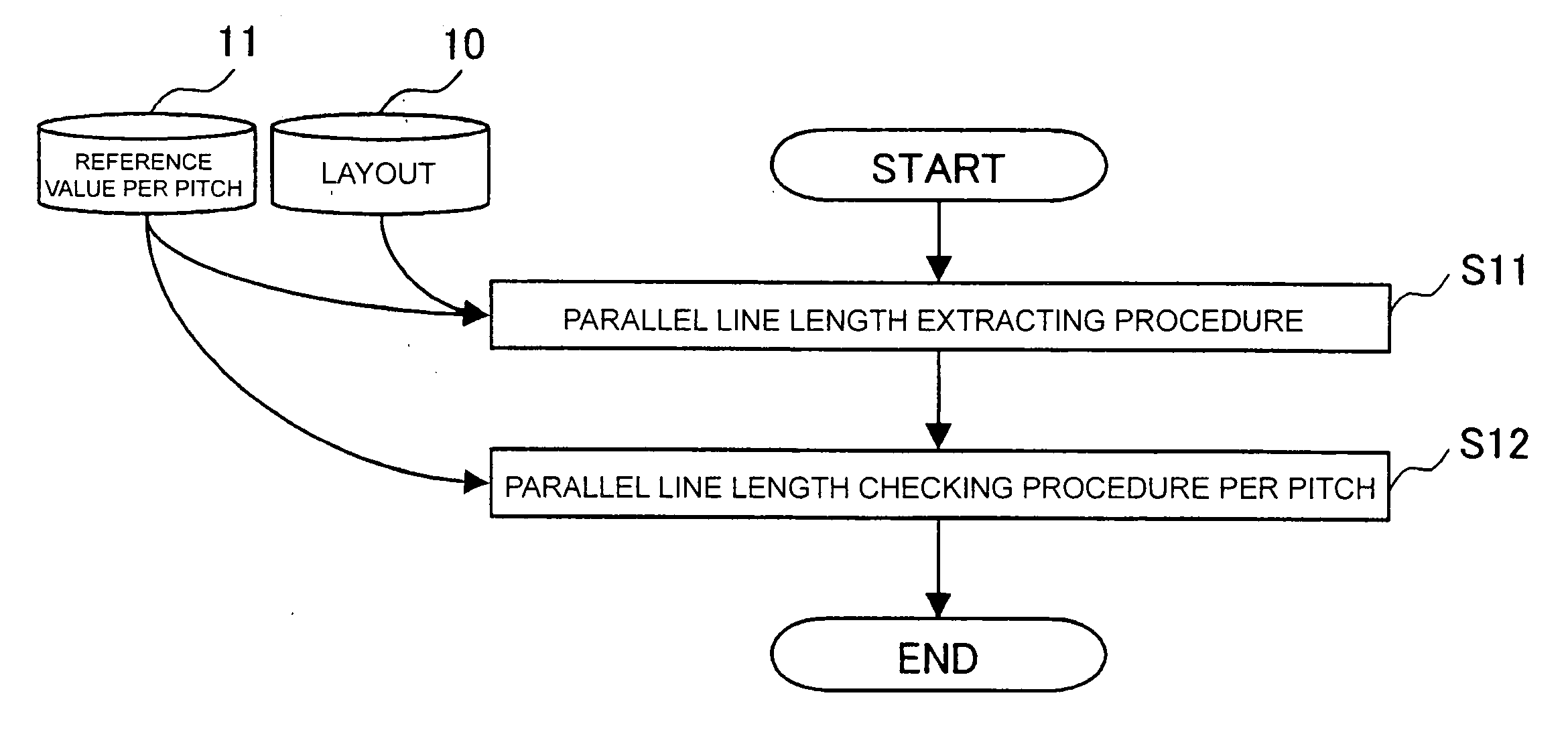
[0059]FIG. 1 is a flowchart illustrating the technique for varying a restriction value of a parallel line length as a determination comparing reference according to a line pitch in determining a portion at which crosstalk occurs in a layout; and FIGS. 2A and 2B are diagrams illustrating specific examples of FIG. 1.

[0060] In FIG. 1, step S11 designates a parallel line length extracting procedure; step S12 denotes a parallel line length checking procedure per pitch; reference numeral 11 designates a reference value per pitch; and reference numeral 10 denotes a layout.

[0061] In FIGS. 2A and 2B, reference characters C11 to C18 designate cells; L11 and L12, parallel line lengths between adjacent lines; T11 and T12, restriction values of the parallel line lengths per pitch, which are described in the reference value 11 per pitch; and D11 and D12, line pitches...

second embodiment

[0069] A description will be given below of a crosstalk checking method in a second embodiment according to the present invention.

[0070]FIG. 3 is a flowchart illustrating the technique for varying a parallel line length for restriction according to drive capability of a line driving cell in determining a portion at which crosstalk occurs in a layout; and FIGS. 4A and 4B are diagrams illustrating specific examples of FIG. 3.

[0071] In FIG. 3, step S21 designates a parallel line length extracting procedure; step S22 denotes a parallel line length checking procedure per drive capability; and reference numeral 12 denotes a reference value per drive capability. In FIGS. 4A and 4B, reference characters C21 to C28 designate cells; L21, a parallel line length as a length at a portion at which adjacent lines to be driven by the cells C21 and C23 are parallel to each other; L22, a parallel line length between adjacent lines to be driven by the cells C25 and C27; and T21 and T22, restriction ...

third embodiment

[0078] A description will be given below of a crosstalk checking method in a third embodiment according to the present invention.

[0079]FIG. 5 is a flowchart illustrating the technique for checking a parallel line length while paying attention to a clock line in determining a portion at which crosstalk occurs in a layout; and FIGS. 6A and 6B are diagrams illustrating specific examples of FIG. 5.

[0080] In FIG. 5, step S31 designates a parallel line length extracting procedure; step S32 denotes a clock net extracting procedure; step S33, an aggressor / victim determining procedure; reference numeral 14, a net list; and reference numeral 15, information on inclination of a signal waveform of each of cells. In FIGS. 6A and 6B, reference characters C31 and C32 designate cells on a clock line; C33 and C34, cells on a normal signal line; K31, an inclination of a signal waveform at an output terminal of the cell C31; K33, an inclination of a signal waveform at an output terminal of the cell ...


PUM


Abstract

In a parallel line length extracting procedure, a layout and a reference value per pitch describing a restriction value of a parallel line length different according to a line pitch are input, thereby extracting the parallel line length between adjacent lines. In a parallel line length checking procedure per pitch, a line pitch is calculated with respect to the adjacent lines extracted in the parallel line length extracting procedure, the parallel line length between the adjacent lines is compared with the reference value per pitch, and thus, a portion at which crosstalk occurs is determined in the case where the parallel line length is greater.

Description

BACKGROUND OF THE INVENTION [0001] The present invention relates to a crosstalk checking method for checking crosstalk caused by signal transition of either one of adjacent lines between the adjacent lines in an layout design of a semiconductor integrated circuit configured by connecting basic logical cells or functional macro blocks via inter-cell lines. [0002] The prior art will be described in reference to FIGS. 13 to 17. [0003] Crosstalk is a phenomenon generated between adjacent lines, in which a change in signal in one of the adjacent lines influences a signal on the other adjacent line. One example is illustrated in FIGS. 13A, 13B, 14A and 14B. [0004] A path consisting of a drive cell C51, a line L51 and a driven cell C52 is assumed to be an aggressor which gives an influence of crosstalk; in contrast, a path consisting of a drive cell C53, a line L52 and a driven cell C54 is assumed to be a victim which suffers the influence of the crosstalk. [0005]FIG. 13A illustrates a des...

Claims


Application Information

Patent Timeline
IPC IPC(8): G06F17/50G01R29/26G01R31/28G01R31/30H01L21/82
CPCG01R29/26H04B3/487G01R31/3016G01R31/2853H01L21/82
Inventor IWANISHI, NOBUFUSA
Owner PANASONIC CORP
Features
  • R&D
  • Intellectual Property
  • Life Sciences
  • Materials
  • Tech Scout
  • Unparalleled Data Quality
  • Higher Quality Content
  • 60% Fewer Hallucinations
Learn More