
Automated monitoring for clinching joints

a technology of automatic monitoring and clinching joints, applied in the direction of manufacturing tools, mechanical equipment, forming safety devices, etc., can solve problems such as inacceptable joints

Active Publication Date: 2006-11-02
NEWFREY
View PDF9 Cites 8 Cited by
  • Summary
  • Abstract
  • Description
  • Claims
  • Application Information

AI Technical Summary

Benefits of technology

[0004] The present invention provides a system for monitoring the performance of clinching apparatus of the type just described, for...

Problems solved by technology

While such clinching apparatus is capable of making excellent clinched joints, there are occasions when the joints are unacceptable, because, for example, the bottom of the joint button is too thin.

Method used


Image

  • Automated monitoring for clinching joints
  • Automated monitoring for clinching joints
  • Automated monitoring for clinching joints

Examples


Embodiment Construction

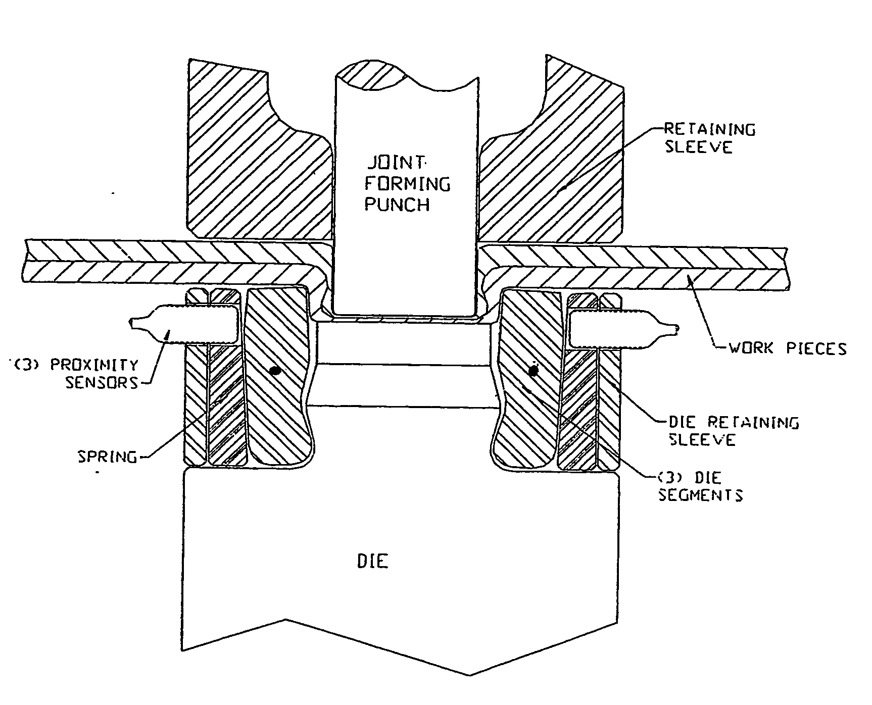
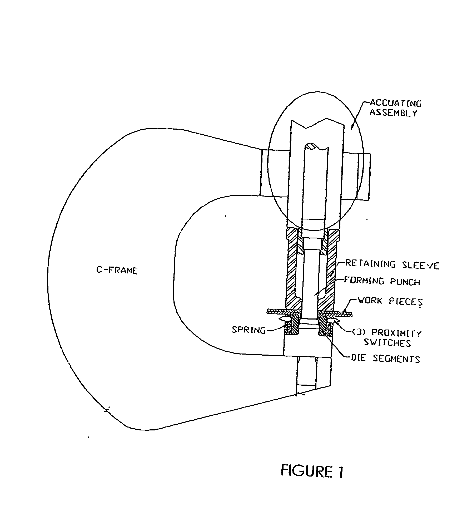
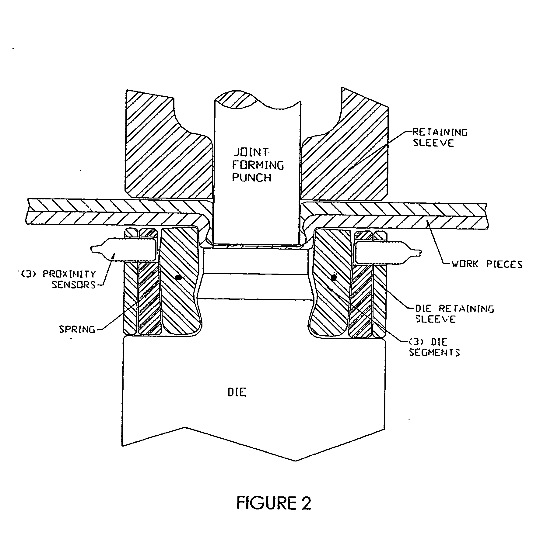
[0013] As shown in FIGS. 1 and 2, a machine or apparatus suitable for implementing the invention may comprise a C-Frame, an Actuating Assembly (actuator) mounted on the C-Frame, a Forming Punch supported on the C-Frame for reciprocative movement in a Retaining Sleeve toward and away from a Joint Forming Die (see FIG. 2) and a Controller (see FIG. 4) preferably including a microprocessor. In one embodiment, the Actuating Assembly mounted on the C-Frame is powered by an electrical servo motor, and transfers rotational motion of a planetary roller screw into linear motion of the joint Forming Punch. U.S. Pat. No. 6,502,008 issued Dec. 31, 2002 discloses an example of an actuating assembly suitable for use in the present invention.

[0014] In the embodiment shown in FIGS. 1 and 2, the control of button diameter utilizes a sensor device including individual proximity switch sensors that sense displacement of pivoting die segments (e.g. three die segments equally spaced circumferentially) ...


PUM

PropertyMeasurementUnit
Timeaaaaaaaaaa
Diameteraaaaaaaaaa
Displacementaaaaaaaaaa

Abstract

A system and method for monitoring clinched joints senses lateral displacement of die segments during formation of a joint, which depends on joint button diameter. The system determines whether a joint is acceptable by correlating acceptable button diameter with acceptable amount of punch advancement. A predetermined number of unacceptable joints indicates excessive punch and / or die wear.

Description

CROSS-REFERENCE TO RELATED APPLICATION [0001] This application claims the benefit of Application No. 60 / 447,284 filed Feb. 14, 2003, incorporated herein by reference.BACKGROUND OF THE INVENTION [0002] This invention is concerned with clinched joints, and more particularly, with automated monitoring of clinching to ensure the quality of clinched joints, including, but not limited to, the quality of button diameter and button bottom thickness. [0003] Among the well-known ways of joining sheets of metal are so-called clinched joints in which the operation of a punch relative to a die deforms contiguous metal sheets in a manner that produces a joint button interlocking the sheets. One form of clinching apparatus uses a die having die segments that are displaced laterally relative to a die anvil during formation of a joint. See, e.g., U.S. Pat. No. 5,150,513 issued Sep. 29, 1992 and U.S. Pat. No. 5,581,860 issued Dec. 10, 1996. While such clinching apparatus is capable of making excellen...

Claims


Application Information

Patent Timeline
IPC IPC(8): B21D55/00B21D39/03B23Q17/00F16BF16J1/00
CPCB21D39/031Y10T29/53065Y10T29/49764Y10T29/53022
Inventor ZDRAVKOVIC, SRECKORAMASAMY, SIVAKUMAR
Owner NEWFREY
Learn More