Method and apparatus for absolute optical encoders with reduced sensitivity to scale or disk mounting errors

an absolute optical encoder and scale technology, applied in the field of absolute optical encoders, can solve the problems of inability to accurately detect the position of the object, inability to accurately detect the position,

Active Publication Date: 2006-11-02
TRIMBLE INC
View PDF4 Cites 35 Cited by
  • Summary
  • Abstract
  • Description
  • Claims
  • Application Information

AI Technical Summary

Problems solved by technology

Incremental encoders can detect only relative position thus the position count can be “lost” in the event of a power failure or by severe jarring resulting in inadvertent disk movement.
One drawback of the invention is that it employs an older quadrature detection technique that is can be relatively susceptible to errors and limited in resolution.
Another disadvantage of this arrangement is that it uses a large number of components that must be accurately aligned and assembled, and the use of separate sensors to read the absolute and incremental tracks respectively further complicates alignment issues.
Moreover, it requires the use of optical lenses, which adds to the cost and complexity of the manufacturing process and precludes its use in some relatively small applications.
However, a drawback of this configuration is that it is not very flexible i.e. the period of the image of the incremental track must match the spatial frequency of the sinusoidal shape almost exactly or accuracy is lost.
This can happen when the disk is jarred causing it to move inadvertently, or by inaccurate disk mounting.
A further disadvantage is that the reference period is fixed by virtue of being embedded in the chip, which cannot change during operation.
Moreover, the use of the specialized ASIC detector adds to the overall cost to the encoder and limits production in large quantities.

Method used


Image

  • Method and apparatus for absolute optical encoders with reduced sensitivity to scale or disk mounting errors
  • Method and apparatus for absolute optical encoders with reduced sensitivity to scale or disk mounting errors
  • Method and apparatus for absolute optical encoders with reduced sensitivity to scale or disk mounting errors

Examples


first embodiment

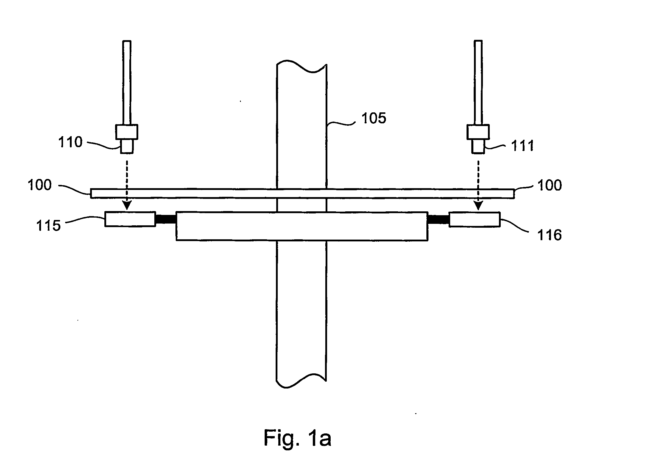
[0025]FIG. 1a depicts a simplified side view illustration of the basic components of a rotary optical encoder operating in accordance with the invention. A disk 100 is mounted on a shaft 105 that rotates about the shaft axis in direct relationship with the item being monitored. The disks used in rotary optical encoders are typically composed of a glass, plastic, ceramic, or metal that have coded markings precisely embedded in a track that encircles the outer portion of the disk. The markings are detected by an arrangement comprising a photoemitter light source 110,111 mounted on one side of the disk 100 and photo detectors 115,116 mounted on the other side of the disk. The disk may be of a construction having an opaque background with transparent markings so that the light passing through the transparent markings is detected. Alternatively, the disk can be transparent with opaque markings, in which case the photo detectors detect the interruption of light by the passing markings.

[00...

second embodiment

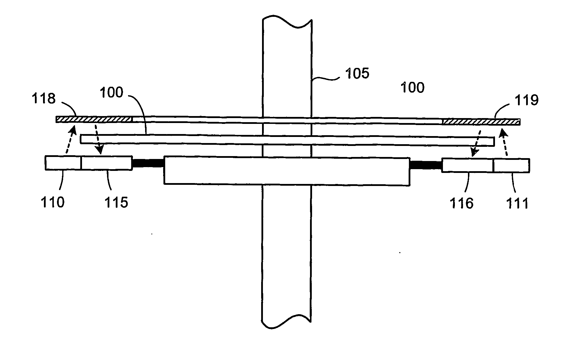
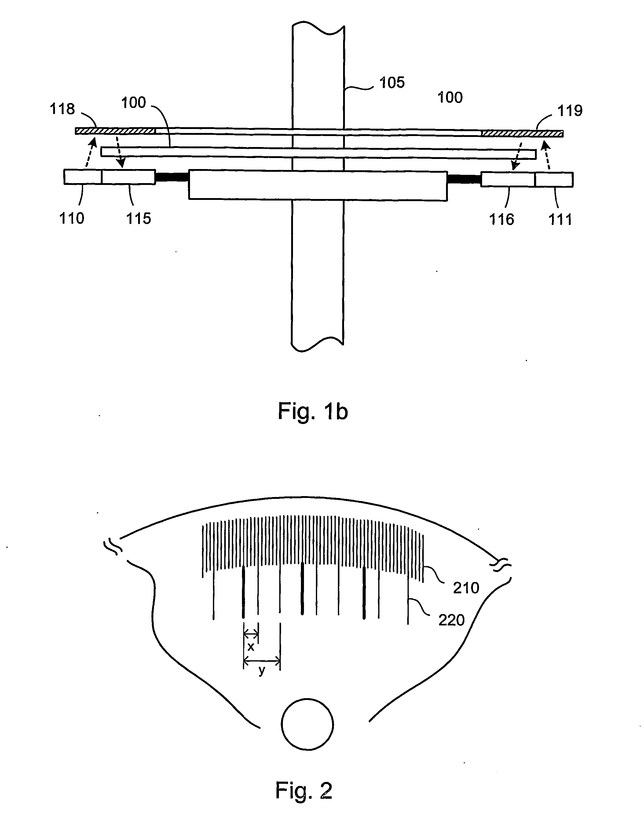
[0027]FIG. 1b depicts a side view of the rotary optical encoder operating in accordance with the invention. The arrangement here is configured so that the photoemitter light source and photo detector (110,115 and 111,116) is proximally located to each other and on the same side of the disk. In fact the laser and the sensor can be incorporated on the same integrated circuit chip, although this is not necessary. In the preferred embodiment, the light source 110,111 is located slightly outside the disk 100 such that the emitted light is reflected by mirror 118,119 through the disk and markings, which are detected by the photo detector 115,116. It should be noted that the invention is not limited to this configuration and that other configurations are possible such as locating both the light source underneath the disk rather than slightly outside of it or conversely locating the sensor slightly outside the disk instead of the light source, for example.

[0028] The photo detectors comprise...


PUM


Abstract

An absolute optical encoder apparatus for measuring an absolute position comprises an optical disk or scale element (100) having both incremental and absolute code tracks formed thereon. In the embodiment, a photoemitter light source (110, 111) illuminates the tracks onto a CCD area array sensor (115, 116) such that an image is formed from a pixel matrix having of rows and columns. Two detector line rows (410, 420) of the pixel matrix are each read out from the portion of the matrix comprising the incremental and absolute code tracks respectively. Inaccurate mounting of the disk or scale element can cause fluctuations in the period of the code tracks resulting from the rotation of the disk or movement of the scale element. The mounting inaccuracies are compensated for either by matching the spatial frequency by dynamically changing row of detector line read from the incremental image of the code track or by altering the numerical value of the pattern period used in the Fourier phase algorithm. The absolute position is numerically calculated from the imaged code tracks.

Description

FIELD OF THE INVENTION [0001] The present invention relates generally to absolute optical encoders and, more particularly, to a high resolution encoding method and apparatus having adaptive compensation for reducing sensitivity to scale or disk mounting errors. BACKGROUND OF THE INVENTION [0002] Optical encoders are electromechanical devices used typically for measuring position or monitoring motion and controlling the position with high precision. They are widely used in applications where extremely accurate linear or angular positioning information is required such as in computer-controlled manufacturing, factory automation, or land surveying equipment. Rotary optical encoders sense angular position by detecting laser light interrupted by markings making up coded tracks embedded on a disk. The disk rotates in sync with the movement being monitored. Rotary encoders are generally classified in either one of two categories i.e. as Absolute or Incremental encoders. Absolute encoders r...

Claims


Application Information

Patent Timeline
Patent Type & Authority Applications(United States)
IPC IPC(8): G01D5/34G01D5/347
CPCG01D5/34707
Inventor NORDENFELT, MIKAELHERTZMAN, MIKAELPALM, STAFFANWESTERMARK, MAGNUS
Owner TRIMBLE INC
Why Eureka
Try Eureka