
Hydrodynamic magnetic seal

a magnetic seal and hydrodynamic technology, applied in the direction of engine seals, mechanical devices, engine components, etc., can solve the problems of reducing friction, generating heat, ring wear, etc., and achieve the effect of reducing friction and reducing friction

Active Publication Date: 2006-11-02
EATON INTELLIGENT POWER LIMITED
View PDF14 Cites 37 Cited by
  • Summary
  • Abstract
  • Description
  • Claims
  • Application Information

AI Technical Summary

Benefits of technology

[0007] It is a further object of this invention to provide such an improved magnetic seal which reduces heat generation.
[0008] It is a further object of this invention to provide such an improved magnetic seal with an increased useful life.
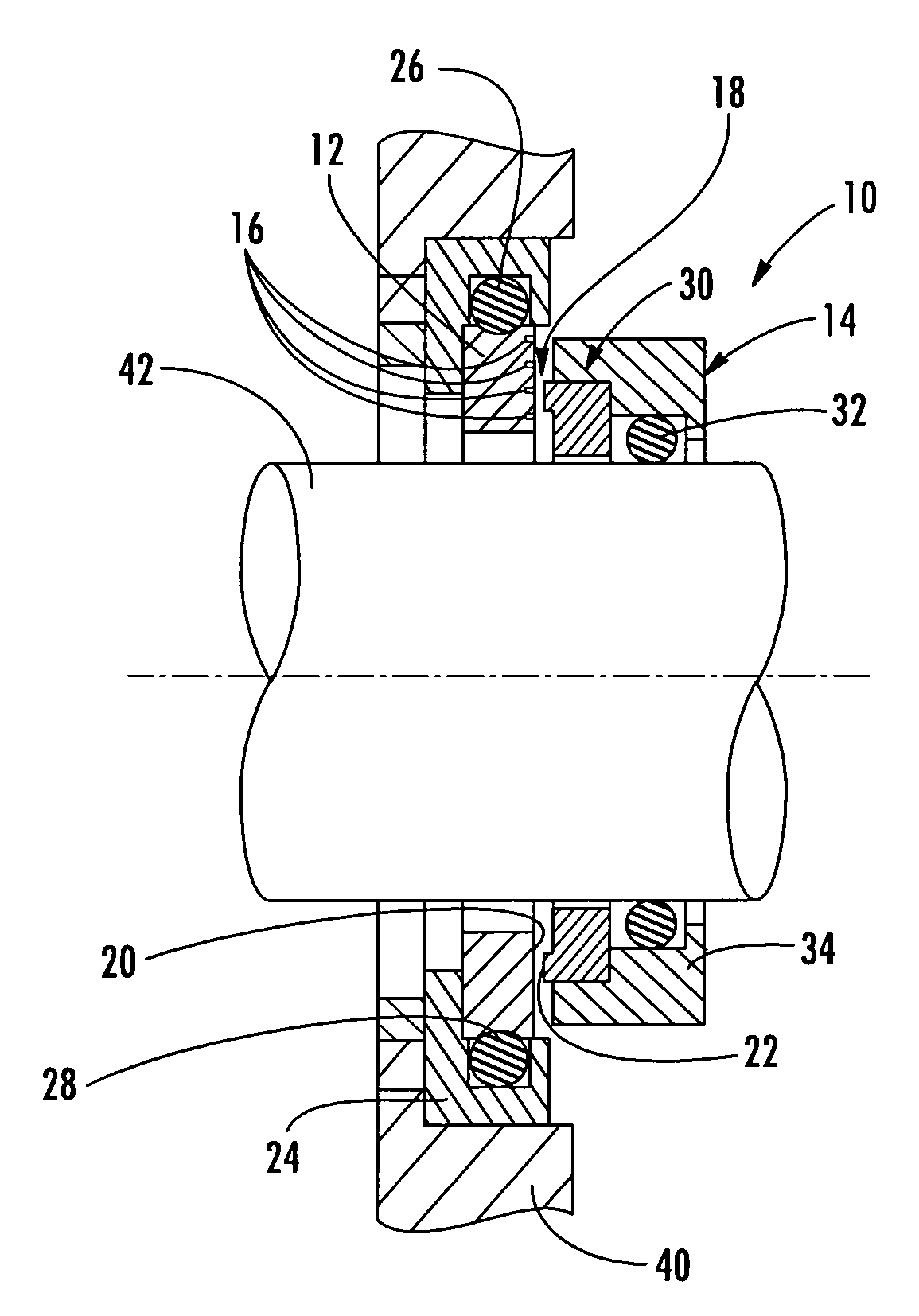
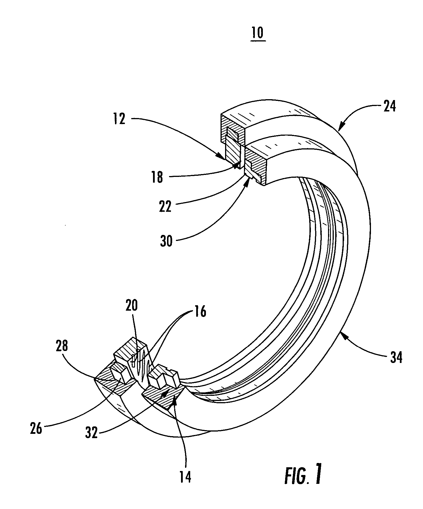
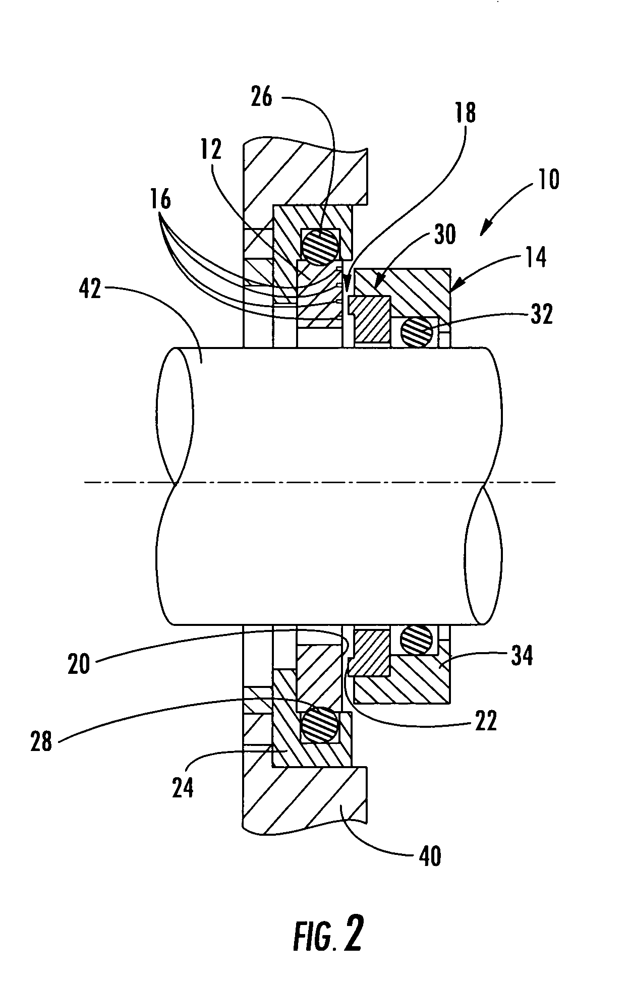
[0009] In one example, the invention results from the realization that if the stationary magnetic sealing or “mating” ring includes hydrodynamic grooves to produce a thin separation film between the stationary magnetic mating ring and the rotating sealing ring, friction, heat, and wear of the magnetic seal are all reduced.
[0014] This invention further features a hydrodynamic magnetic seal including a stationary magnetic mating ring fixed within a stationary insulator and a rotary sealing ring fixed to a rotating shaft proximate the stationary magnetic mating ring and attracted to the magnetic mating ring. The rotary sealing ring includes a carbon component. The magnetic mating ring and / or the sealing ring include hydrodynamic grooves configured to create a separation film therebetween to reduce friction.
[0015] This invention also features a hydrodynamic magnetic seal including a stationary magnetic mating ring including an annular sealing face, an insulator about the stationary magnetic mating ring, and a rotary sealing ring attracted to the magnetic mating ring. The rotary sealing ring has an annular sealing face including a carbon element. The annular sealing face of the magnetic mating ring and / or the rotating sealing ring includes hydrodynamic grooves configured to pump a gas between the sealing faces and create a separation film therebetween to reduce friction.

Problems solved by technology

For example, during operation the sealing faces contact each other, causing friction and generating heat.
Consequently, the rings wear.
The carbon element reduces but does not eliminate friction.
Also, the carbon element can blister, causing further friction and heating.
Thus, the effectiveness of the seal is decreased.
Moreover, in the example where oil is the liquid to be sealed, the heat generated by the face seal can degrade the oil and result in a buildup of grime or “coking”.
In each of these cases, the effectiveness of the seal is reduced, and in the worst case, catastrophic failure of the magnetic seal may occur.

Method used


Image

  • Hydrodynamic magnetic seal
  • Hydrodynamic magnetic seal
  • Hydrodynamic magnetic seal

Examples


Embodiment Construction

[0028] Aside from the preferred embodiment or embodiments disclosed below, this invention is capable of other embodiments and of being practiced or being carried out in various ways. Thus, it is to be understood that the invention is not limited in its application to the details of construction and the arrangements of components set forth in the following description or illustrated in the drawings. If only one embodiment is described herein, the claims hereof are not to be limited to that embodiment. Moreover, the claims hereof are not to be read restrictively unless there is clear and convincing evidence manifesting a certain exclusion, restriction, or disclaimer.

[0029] Industrial seals, particularly mechanical end face seals, have been developed for a variety of industries and for a number of devices such as gas turbines, gearboxes, engines, pumps, and the like. Generally, mechanical face seals seal the space between a housing and a rotating shaft which passes through the housing...


PUM


Abstract

A hydrodynamic magnetic seal includes a magnetic mating ring and a sealing ring attracted to the magnetic mating ring. The magnetic mating ring and / or the sealing ring include hydrodynamic grooves configured to create a separation film between the magnetic mating ring and the sealing ring to reduce friction.

Description

FIELD OF THE INVENTION [0001] This invention relates to an improved magnetic seal, and more particularly to a magnetic seal including hydrodynamic grooves useful in rotating machinery such as turbines and in other applications. BACKGROUND OF THE INVENTION [0002] Mechanical face seals are widely used to provide a seal between a stationary housing, often containing a lubricant such as oil, and a rotating shaft which passes through the housing. Typically, such seals include a stationary sealing ring about the shaft but fixed to the housing. Another sealing ring is mounted on and rotates with the rotating shaft. The seal face of the rotating sealing ring or the stationary sealing ring may include grooves of some type. These grooves form a layer of air between the sealing ring faces during operation. In these “hydrodynamic” seals, the sealing faces of both sealing rings are biased together by mechanical means that may include a spring. [0003] In a magnetic face seal, in contrast, the sta...

Claims


Application Information

Patent Timeline
Patent Type & Authority Applications(United States)
IPC IPC(8): F16J15/43
CPCF16J15/3444F16J15/3412
Inventor VILLENEUVE, MICHEL LAURENTZHENG, XIAOQING
Owner EATON INTELLIGENT POWER LIMITED
Learn More