Heavy-duty vehicle axle/suspension system

a suspension system and heavy-duty technology, applied in the direction of resilient suspension, interconnection system, vehicle spring, etc., can solve the problems of unfavorable axle/suspension system, unfavorable axle/suspension system, and undesired trailer removal, etc., to achieve cost-effective effects

Inactive Publication Date: 2006-11-02
HENDRICKSON USA L L C
View PDF37 Cites 39 Cited by
  • Summary
  • Abstract
  • Description
  • Claims
  • Application Information

AI Technical Summary

Benefits of technology

[0017] An objective of the present invention is to provide an axle/suspension system for a heavy-dut

Problems solved by technology

At this stage of the loading or unloading process, a disadvantage of many prior art axle/suspension systems occurs, which is an event known in the art as “dock walk.” The dock walk event will be described in greater detail below, but may be summarized as a generally arcuate motion of the rigid trailing arm beam and axle of the axle/suspension system in response to the sudden weight increase of the fork lift driving into the trailer, which causes the vehicle tires to rotate in a forward direction and undesirably move the trailer away from the loading dock.
However, components such as a structural stop and/or exhaust valves, as well as associated components for the operation and control of the stop and/or valves, involve an undesirable increase in weight of the axle/suspension system, as well as an undesirable increase in cost for the system.
Moreover, such additional components add to the complexity of the axle/suspension system, undesirably increasing maintenance costs for the system.
However, such prior art parallelogram linkage axle/suspension systems possess a distinct disadvantage, which is a lack of stiffness or rigidity that creates an inherent lack of roll stability.
In order to provide stability, an auxiliary roll bar asse

Method used


Image

  • Heavy-duty vehicle axle/suspension system
  • Heavy-duty vehicle axle/suspension system
  • Heavy-duty vehicle axle/suspension system

Examples


first embodiment

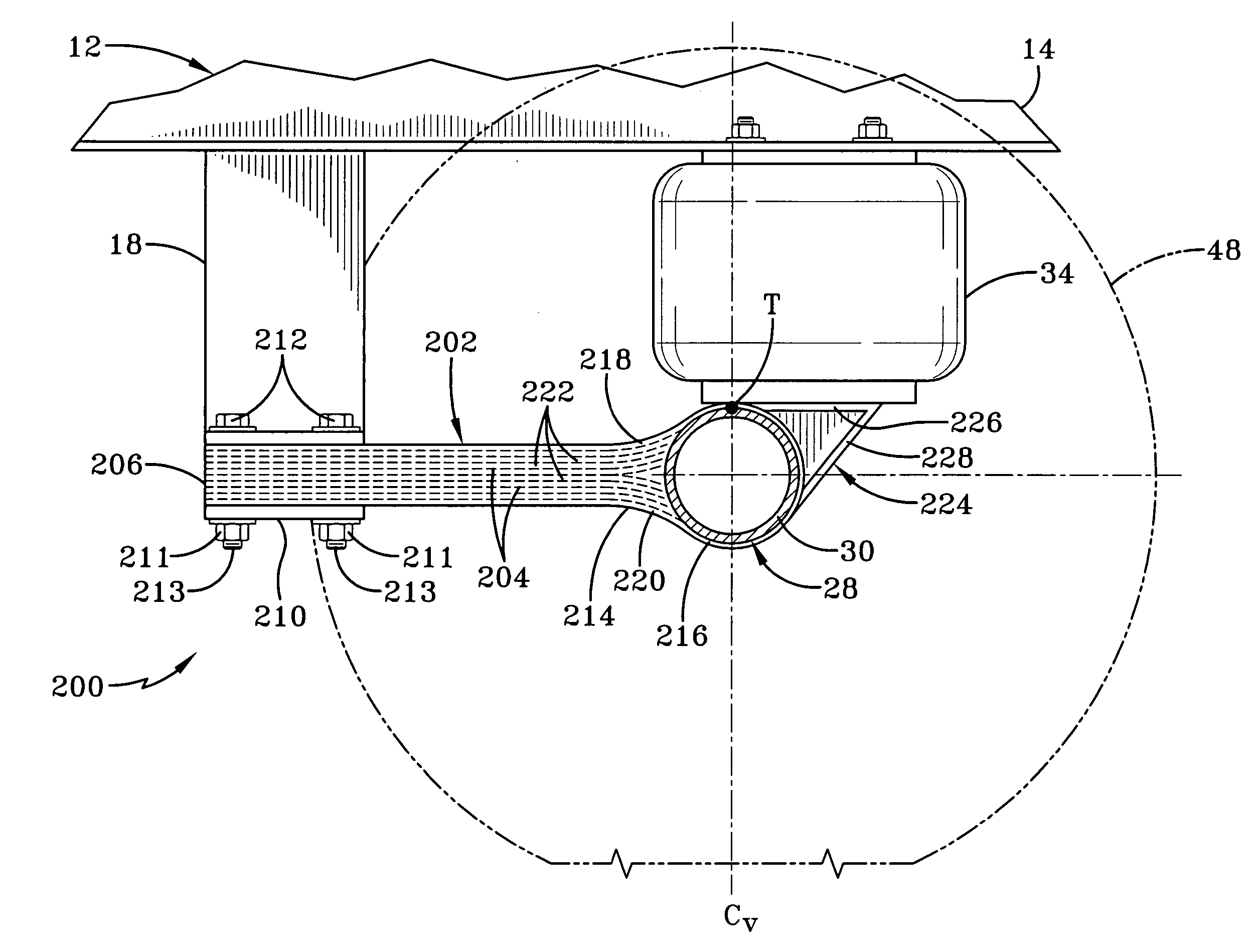
[0064] With particular reference to FIG. 6, first embodiment axle / suspension system 200 includes a beam 202 that includes a plurality of fiber-reinforced composite mats 204. For example, beam 202 preferably includes from about three to twenty mats, which are stacked horizontally to form an integral beam structure. Mats 204 are engineered to meet application-specific design requirements, such as spring rate and strength, as known to those skilled in the art of composite design. Mats 204 include a reinforcing material, such as glass fibers, carbon fibers, or other known reinforcing materials, which are resistant to tensile stretching. The fibers are dispersed in a polymeric or metallic matrix that is generally flexible, as known in the art of composite material design. Preferably, the fibers generally are more dimensionally stable than the matrix, which contributes to the advantages of beam 202, which are described in detail below.

[0065] Beam 202 preferably has a substantially constan...

second embodiment

[0085] With particular reference to FIGS. 10 and 11, second embodiment axle / suspension system 320 preferably includes a pair of longitudinally-extending, transversely-spaced parallel beams 322, each of which is generally rigidly attached to a respective one of a transversely-spaced pair of hangers 18 and extends rearwardly therefrom to immovably capture axle 28, as will be described in greater detail below. It should be noted that, while hanger 18 is sometimes considered to be part of the vehicle frame or subframe once it is connected to members of the frame or subframe, as described above, the hanger is typically engineered as part of axle / suspension system 320.

[0086] Each beam 322 preferably is formed of a fiber-reinforced composite, and is engineered to meet application-specific design requirements, such as spring rate and strength, as known to those skilled in the art of composite design. Each beam 322 includes a reinforcing material, such as glass fibers, carbon fibers, or othe...


PUM


Abstract

An axle/suspension system for a heavy-duty vehicle, in which the vehicle includes a frame that extends in a longitudinal direction relative to the vehicle. The axle/suspension system is attached to the vehicle frame via at least one hanger and includes at least one beam, which includes a first end and a second end. The first end of the beam is connected to the hanger, and the second end of the beam immovably captures an axle, which extends in a transverse direction relative to the vehicle. The beam is formed of a composite material and has a substantially constant cross section in the transverse direction to provide sufficient strength to control roll forces encountered by the vehicle during operation.

Description

CROSS-REFERENCE TO RELATED APPLICATION [0001] This application claims the benefit of U.S. Provisional Patent Application Ser. No. 60 / 676,554, filed on Apr. 29, 2005.BACKGROUND OF THE INVENTION [0002] 1. Field of the Invention [0003] The present invention relates to the art of axle / suspension systems for vehicles. More particularly, the invention relates to the art of trailing or leading arm air-ride axle / suspension systems for heavy-duty vehicles, such as tractor-trailers or semi-trailers, which cushion the ride and stabilize the vehicle during operation. Still more particularly, the invention relates to the art of trailing or leading arm air-ride axle / suspension systems for heavy-duty vehicles of the type that may be susceptible to roll forces and dock walk. [0004] 2. Background Art [0005] Heavy-duty vehicles that transport freight, for example, tractor-trailers or semi-trailers and straight trucks, typically include leading or trailing arm air-ride suspension assemblies that conne...

Claims


Application Information

Patent Timeline
IPC IPC(8): B60G3/22B60G9/00
CPCB60G2204/121B60G2202/152B60G2204/143B60G2204/1432B60G2204/148B60G2204/4302B60G2206/20B60G2206/7101B60G2300/0262B60G5/047B60G9/00B60G9/003B60G11/27B60G11/46B60G11/465B60G21/051B60G2200/21B60G2200/31B60G2200/314B60G2200/318B60G2200/4622B60G2202/112B60G2204/129
Inventor RAMSEY, JOHN EDWARD
Owner HENDRICKSON USA L L C
Why Eureka
Try Eureka