Time synchronization of master and slave devices

a time synchronization and master device technology, applied in the field of time synchronization measurement system, can solve the problems of high cost of procedure, deviation in the ms range, and inability to take into account the effect of time synchronization,

Inactive Publication Date: 2006-11-02
TEKTRONIX INC
View PDF17 Cites 24 Cited by
  • Summary
  • Abstract
  • Description
  • Claims
  • Application Information

AI Technical Summary

Problems solved by technology

A problem arises when the corresponding measurement cards are implemented in different apparatuses, i.e., different protocol testers or monitoring apparatuses.
While this makes the two time measurement devices run synchronously, the problem remains of setting the two time measurement devices to the common time basis, i.e., to a common test time or absolute time.
What is problematic about this is that Information on the common time basis is related to a specific, previously agreed signal that emanates from the time server.
However because of the aforementioned effects, deviations in the ms range may already result between the time measurement devices of the master and slave devices relative to each other.
However this procedure is expensive and does not take into consideration that in many environments there is no access to a GPS antenna.

Method used


Image

  • Time synchronization of master and slave devices
  • Time synchronization of master and slave devices
  • Time synchronization of master and slave devices

Examples


Embodiment Construction

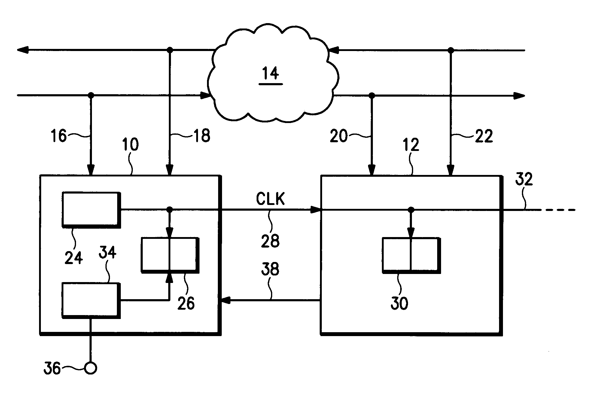
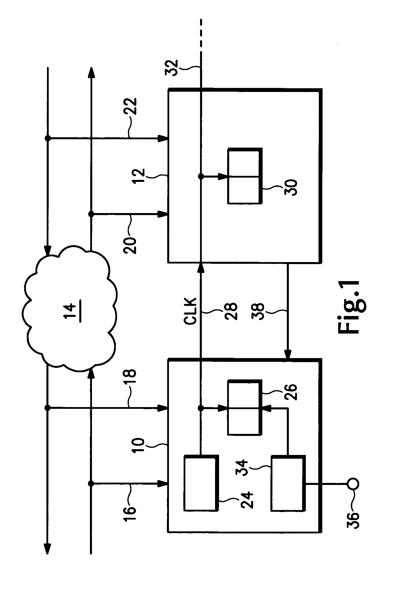
[0022] Referring now to FIG. 1, an embodiment of a measurement system according to the present invention is shown in which a master device 10 and a slave device 12 are connected to a communication network 14. The master device 10 receives information, particularly measurement information, from the communication network 14 via a first line 16 and a second line 18, and the slave device 12 receives information, particularly measurement information, from the communication network 14 via third and fourth lines 20 and 22. The master device 10 includes a reference clock pulse-generating device 24 that provides a reference clock signal, Clk, to a time measurement device 26, such as a clock, mounted inside the master device. The reference clock signal, Clk, is transmitted from the master device 10, preferably DC-free, via a clock line 28 to the slave device 12. In the slave device 12 the reference clock signal is input to a time measurement device 30. The reference clock signal is provided a...


PUM


Abstract

A time synchronized measurement system has a master device and a slave device. The master device and the slave device each have a time measurement device for assigning a corresponding time of sending and / or receiving a piece of measurement information. The master device also has a reference clock pulse-generating device for transmitting a reference clock signal to the slave device. The reference clock signal is modulated by a piece of information on a common time basis for the master device and the slave device.

Description

BACKGROUND OF THE INVENTION [0001] The present invention relates to a time synchronized measurement system, and more particularly to a system for time synchronizing a master device and a slave device. In the field of protocol measurement, protocol testers and monitoring apparatuses are used which send and receive protocol messages or only receive protocol messages. In order to be able to draw desired conclusions with regard to problems occurring during transmission, the protocol messages are given a time stamp when sent and received, and are stored. In this process different switching units may be responsible for different protocol messages so that with respect to the time stamp there are no problems when the different switching units are different measurement cards of a protocol tester or monitoring apparatus. A time basis, such as a test time or absolute time, may be defined within the protocol tester or monitoring apparatus. The test time forms a common time basis for all measure...

Claims


Application Information

Patent Timeline
Patent Type & Authority Applications(United States)
IPC IPC(8): H03K3/00
CPCG01R13/0254H04L43/18H04L7/0008G01R13/32G06F13/14
Inventor FOERSTER, SVENSCHMACK, STEFFENSCHURICHT, MICHAELVOLLMER, HANS-ULRICH
Owner TEKTRONIX INC
Why Eureka
Try Eureka