GNSS line bias measurement system and method

a line bias and measurement system technology, applied in wave based measurement systems, instruments, navigation instruments, etc., can solve problems such as inability to address changes in line bias, and cannot be real-tim

Active Publication Date: 2006-11-02
NOVARIANT
View PDF23 Cites 43 Cited by
  • Summary
  • Abstract
  • Description
  • Claims
  • Application Information

AI Technical Summary

Benefits of technology

[0018] According to this embodiment of the invention, the intermediate frequency signal is approximately one-half the frequency of the carrier signals. By making this selection, the position detection system is no longer sensitive to line bias.

Problems solved by technology

The problem with these existing solutions for deriving the line bias is that they are not real-time.
Furthermore, these solutions, since they involve time averages, typically cannot address changes in the line bias due to variations shorter than the period over which the averages are made, such as from thermal effects, for example.

Method used


Image

  • GNSS line bias measurement system and method
  • GNSS line bias measurement system and method
  • GNSS line bias measurement system and method

Examples


Embodiment Construction

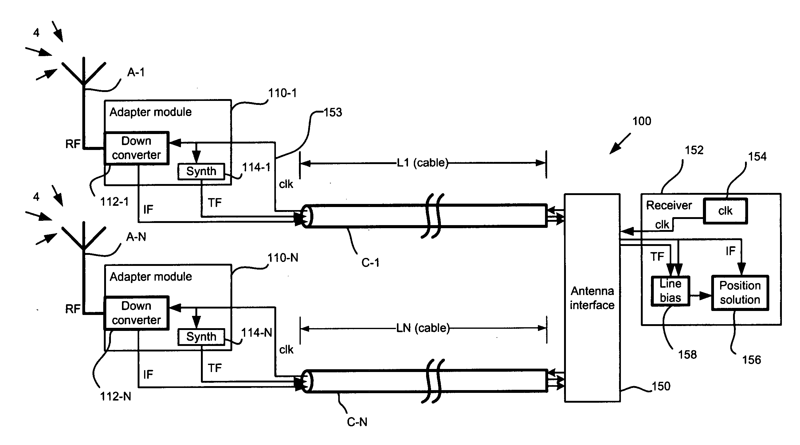
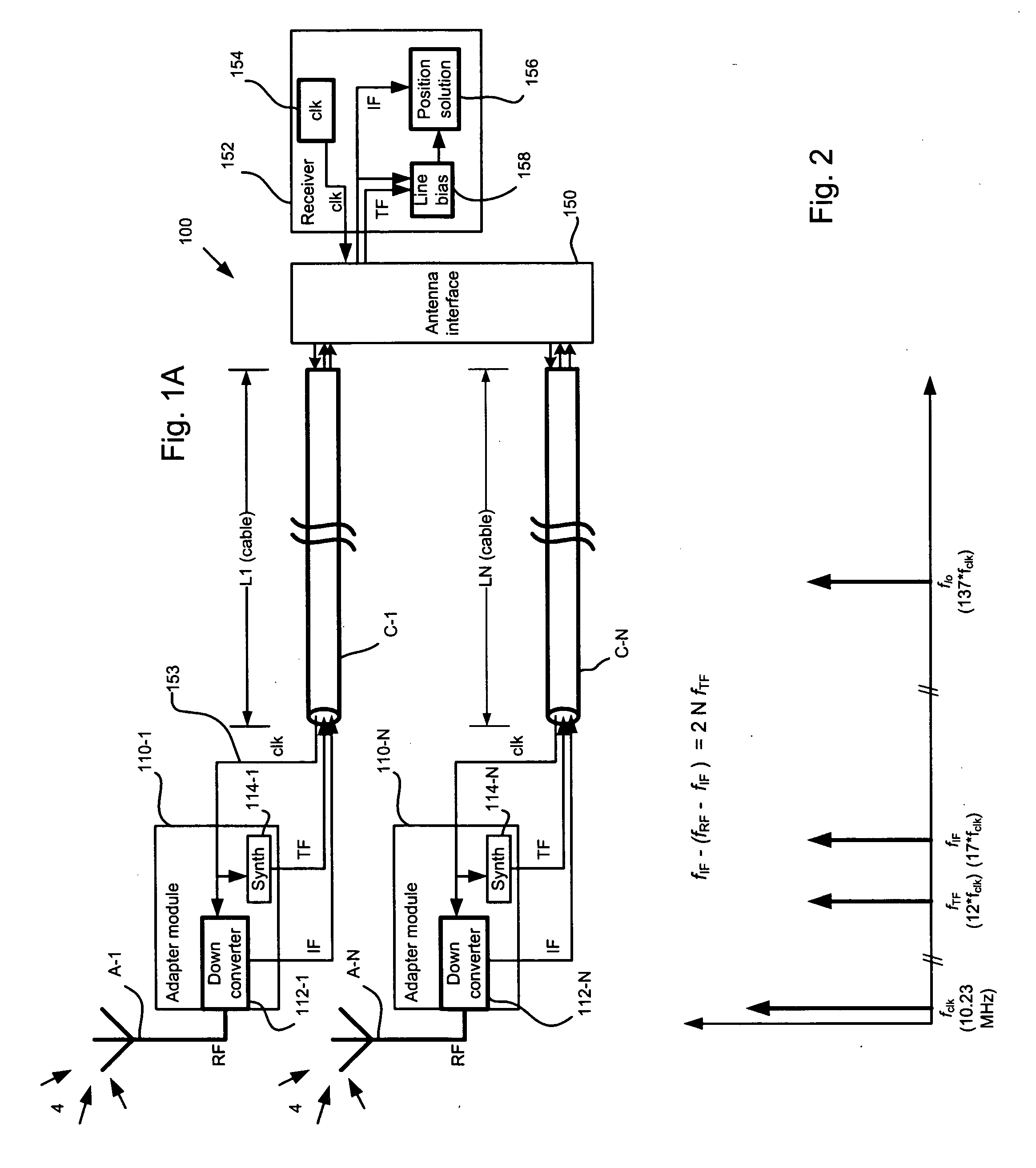
[0034]FIG. 1A is a schematic block diagram showing a differential GPS system providing for line bias measurement and compensation, which system has been constructed according to the principles of the present invention.

[0035] In more detail, the position detection system 100 generally comprises a series of antennas A-1 to A-N. At least one antenna is required, whereas many systems can also include two or more antennas. These antennas A-1 to A-N receive carrier signals 4, typically from a satellite positioning or navigation system such as the GNSS and / or from one or more ground-based transmission sources such as pseudolites. Such carrier signals can actually come from many radio frequency (RF) sources, including those not intended for navigation. Such transmitters would include, but not be limited low earth orbiting (LEO) satellites or high definition television (HDTV) broadcast stations.

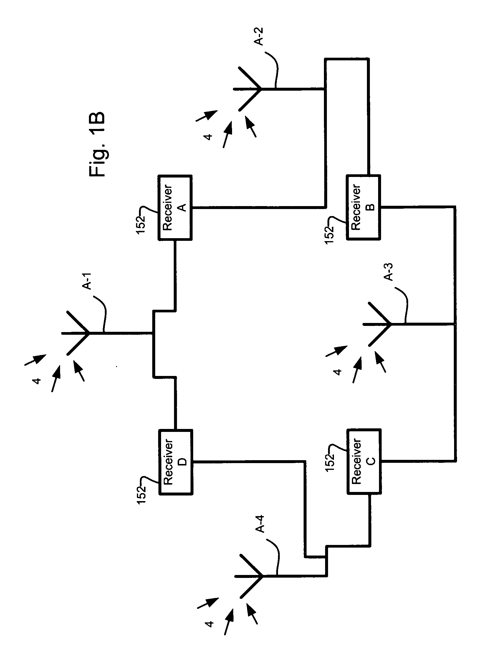
[0036] The antennas A-1 to A-N communicate with a common receiver 152, although in other configu...


PUM


Abstract

A number of solutions for deriving the line bias are disclosed. Some of these solutions utilize signal processing and judicious selection of the frequency plan used in the position detection systems to either enable the derivation of the line bias, or make the measurements insensitive to line bias. In other examples, the present invention utilizes measurement schemes for deriving the line bias and enabling a position detection system to process line bias information in order to find a position solution

Description

BACKGROUND OF THE INVENTION [0001] The NAVSTAR Global Positioning System (GPS) is a satellite-based navigation system developed by the U.S. military in the 1970's. The GPS space segment consists of a nominal constellation of 24 satellites, four satellites in each of 6 orbit planes. [0002] Originally conceived as a navigation aid for ships, the use of the system has become ubiquitous both within the military and within civilian and commercial applications. For example, many cars today are outfitted with GPS navigation systems that locate the car on a displayed digital map to the driver. In commercial applications, GPS systems are used for surveying in addition to controlling vehicles such as graders during the laying of road beds. On these vehicles, the antennas are sometimes located on the blade in addition to the cab. In order to ensure good satellite visibility, however, the antennas must be placed on high poles to provide line of sight to the required four satellites. [0003] The ...

Claims


Application Information

Patent Timeline
Patent Type & Authority Applications(United States)
IPC IPC(8): G01S5/14H01Q3/22G01S19/46
CPCG01S19/44G01S19/04
Inventor LAWRENCE, DAVID GARYZIMMERMAN, KURTMONTGOMERY, PAUL YALDENCOBB, HENRY STEWART
Owner NOVARIANT
Why Eureka
Try Eureka