Chemical analyzer and cartridge for chemical analyzer

Inactive Publication Date: 2006-11-02
HITACHI HIGH-TECH CORP
View PDF10 Cites 45 Cited by
  • Summary
  • Abstract
  • Description
  • Claims
  • Application Information

AI Technical Summary

Benefits of technology

[0016] According to the present invention, it is possible to not only avoid an error and variation in amount of a dispensed reagent, leakage of the dispe

Problems solved by technology

Therefore, the rotatable structure (disk) is complicated and so is the entire device for realizing the required sequence.
If there is a gap between the filter and the flow channel, the DNA mixed solution flows through the gap, and the DNA in the leaked solution is not recovered on the filter, thus resulting in a reduction of the DNA recovery rate.
The above-described filter mounting method is apt to

Method used


Image

  • Chemical analyzer and cartridge for chemical analyzer
  • Chemical analyzer and cartridge for chemical analyzer
  • Chemical analyzer and cartridge for chemical analyzer

Examples


Example

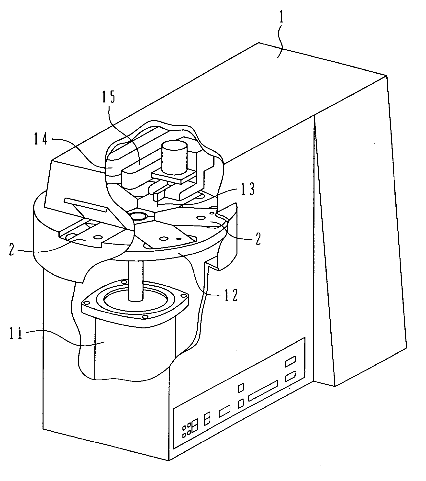
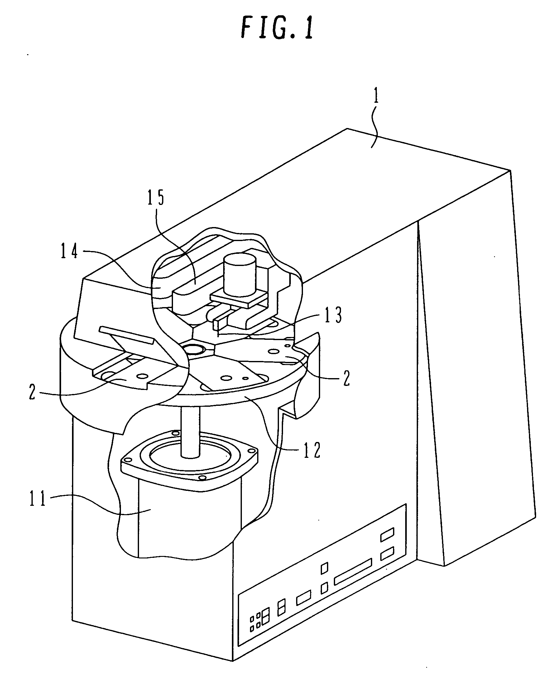
[0041]FIG. 1 shows one example of a chemical analyzer according to the present invention. A chemical analyzer 1 comprises a motor 11, a holding disk 12 rotatable by the motor 11, a plurality of test cartridges 2 disposed on the holding disk 12, a perforator 13 for perforating the test cartridge 2, a heater 14, and a detector 15. An operator prepares the test cartridge 2 for each test item, mounts it to the holding disk 12, and starts the operation of the chemical analyzer 1.

[0042] While in the chemical analyzer of this example the heater 14 and the detector 15 are disposed in separate positions, those two devices may be integrated, as another example, into an integral unit such that heating and detection are performed at the same position. Also, while the heater and the detector are positioned in the upper side of the holding disk 12, either one or both of them may be disposed in the lower side of the holding disk 12.

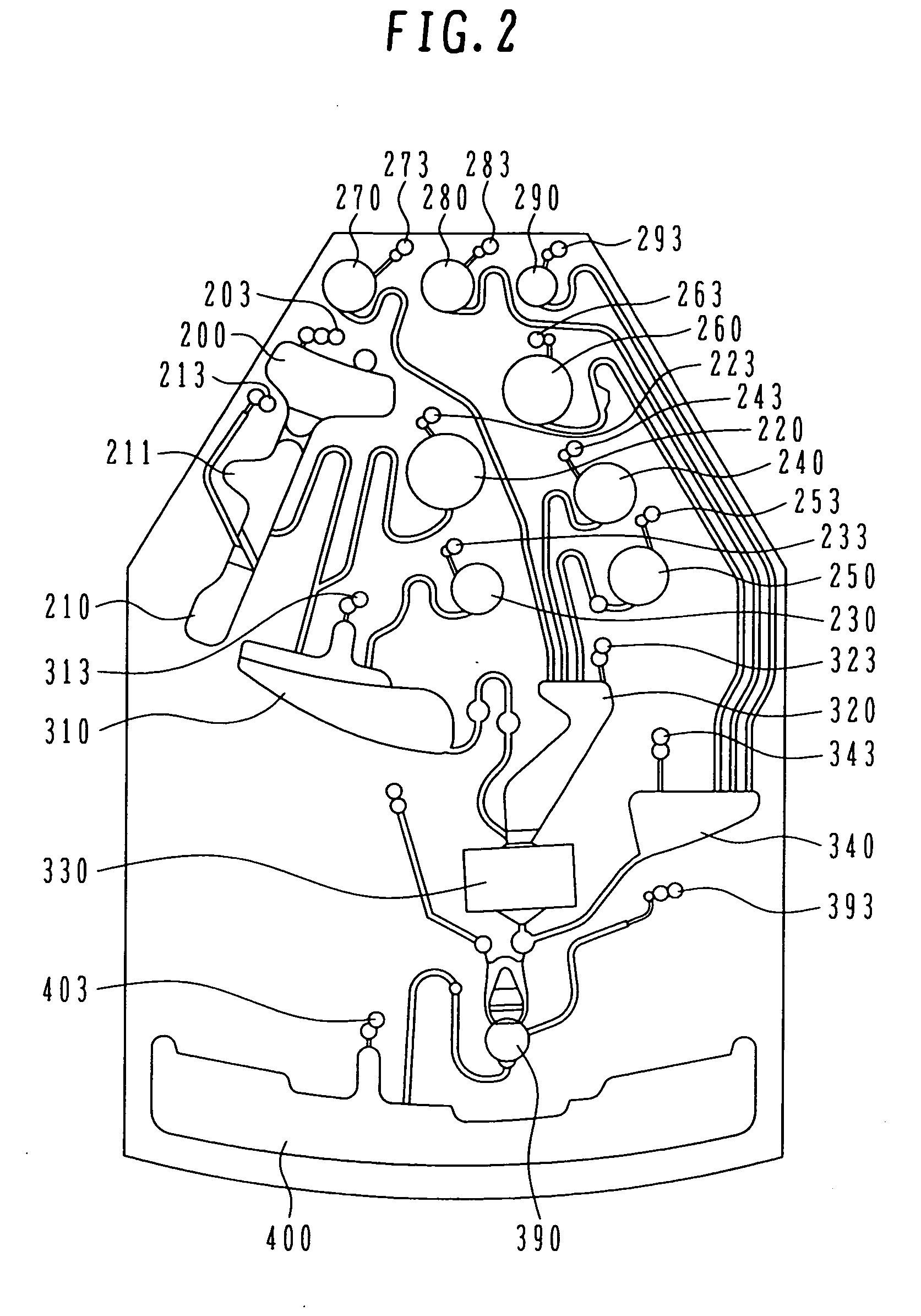
[0043] The structure of the test cartridge 2 will be described b...


PUM


Abstract

A chemical analyzer has a rotatable holding disk, test cartridges disposed thereon, and a detector. The test cartridge includes a base plate having vessels and flow channels. The base plate is covered with a cover for covering the vessels and flow channels. The holding disk is rotated to generate centrifugal force, causing a fluid to be moved from one vessel at the inner peripheral side with respect to a rotation axis of the holding disk to another vessel at the outer peripheral side with respect to the rotation axis via the flow channel. In the test cartridge, at least one reagent port is formed in the base plate, and a closed vessel containing a reagent is placed in the reagent port. The closed vessel is a microcapsule, a plastic closed vessel, or a screw-in closed vessel, for example.

Description

BACKGROUND OF THE INVENTION [0001] 1. Field of the Invention [0002] The present invention relates to a chemical analyzer for performing movement, mixing, etc. of a solution by utilizing centrifugal force, and more particularly to a chemical analyzer using a detachable test cartridge. [0003] 2. Description of the Related Art [0004] JP,A 2003-502656 (WO 00 / 78455) discloses a device for extracting DNA (Doxyribonucleic Acid) from a sample containing the DNA. In the disclosed device, the DNA is captured by feeding the sample containing the DNA to pass through a glass filter. Only the DNA is recovered and collected by feeding a cleaning fluid and an eluant to pass through the glass filter in which the DNA has been captured. The glass filter is attached to a rotatable structure, and reagents, such as the cleaning fluid and the eluant, are held in respective reagent reservoirs within the same structure. Each reagent is caused to flow or move under the action of centrifugal force generated w...

Claims


Application Information

Patent Timeline
IPC IPC(8): G01N35/00
CPCB01L2400/0409B01L2400/0677B01L2400/0683G01N21/07G01N35/00069G01N2035/00495B01L2300/0816B01L3/50273B01L3/502738B01L2200/16B01L2300/021B01L2300/041B01L2300/0672B01L3/502707
Inventor OSONE, YASUOSAITO, MICHIHIROIHARA, HIROKINISHIJIMA, NORIYONAGAOKA, YOSHIHIROWATANABE, NARUOSASAKI, SHIGEYUKIMAKI, NOBUYUKI
Owner HITACHI HIGH-TECH CORP
Why Eureka
Try Eureka