Self-cooling container for liquids

a container and liquid technology, applied in the field of self-cooling containers for liquids, can solve the problems of reduced cooling efficiency, excessive weight, liquid volume displacement loss in containers, etc., and achieve the effect of improving cooling efficiency

Inactive Publication Date: 2006-11-09
SMOLKO DANIEL D +1
View PDF6 Cites 31 Cited by
  • Summary
  • Abstract
  • Description
  • Claims
  • Application Information

AI Technical Summary

Problems solved by technology

Unfortunately, evaporation directly from the outer clay surface eventually lead to scale formation and reduced cooling efficiency as the minerals build up on this surface reducing the liquid permeability and lowering the liquid vapor pressure.
In all these cases the design of the system necessitates that the liquid contents, a separate chamber and / or the shell of the bottle be cooled leading to excessive weight in addition to a liquid volume displacement loss in the container.
Mass transfer of vapor occurs selectively to the gas side of the matrix resulting in the loss of liquid or the loss of select volatile liquid components and the loss of evaporative latent heat.

Method used


Image

  • Self-cooling container for liquids
  • Self-cooling container for liquids
  • Self-cooling container for liquids

Examples


Embodiment Construction

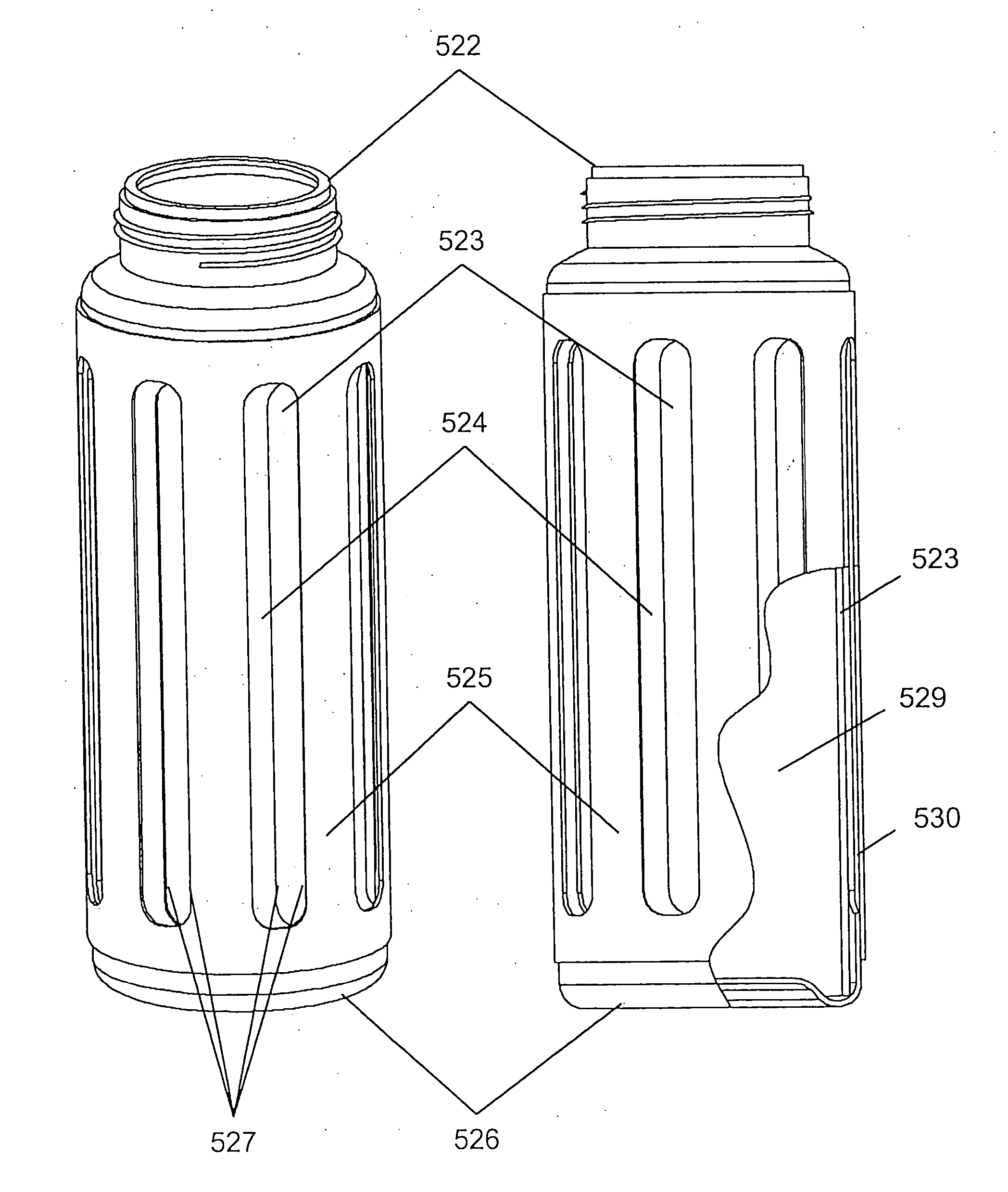
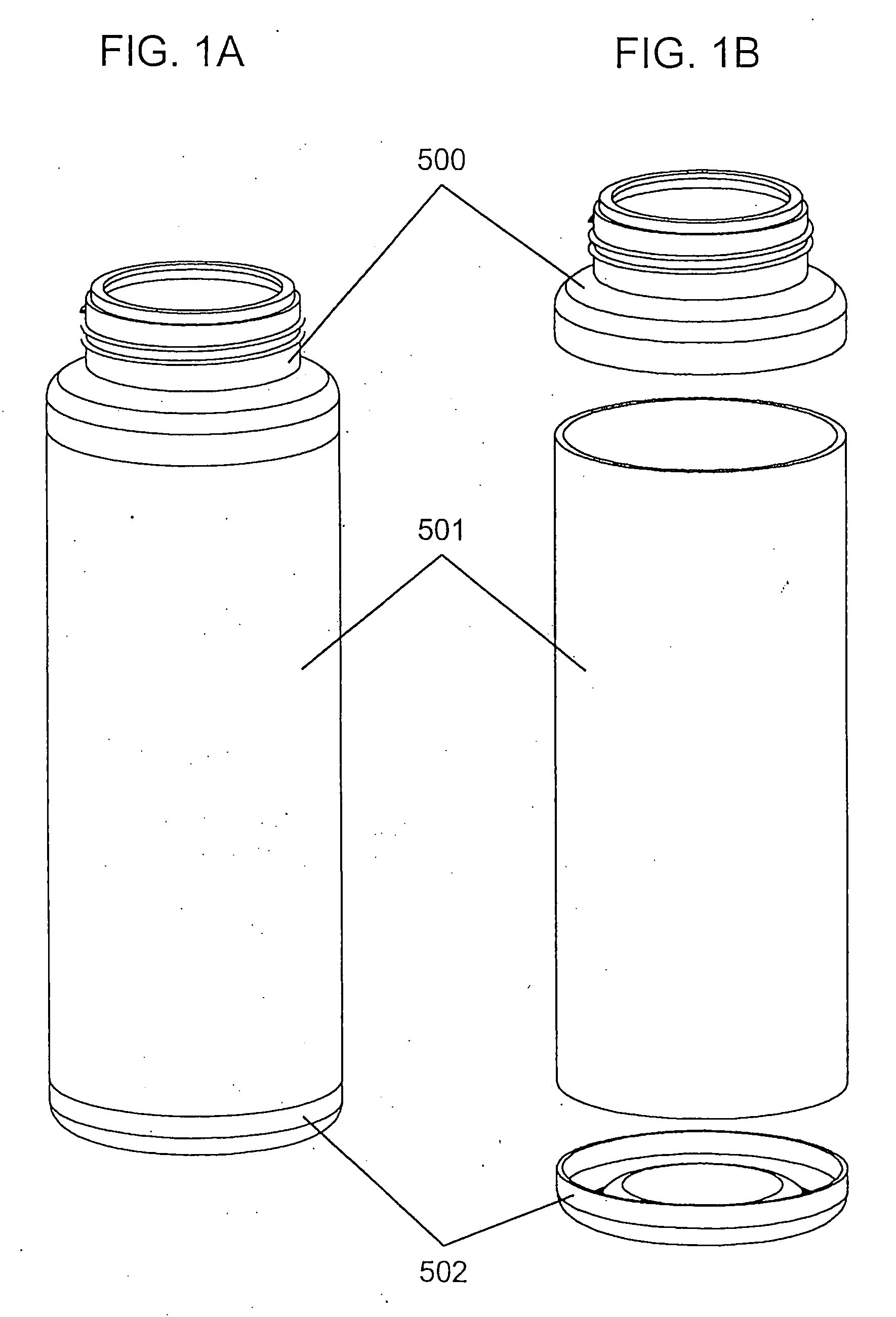
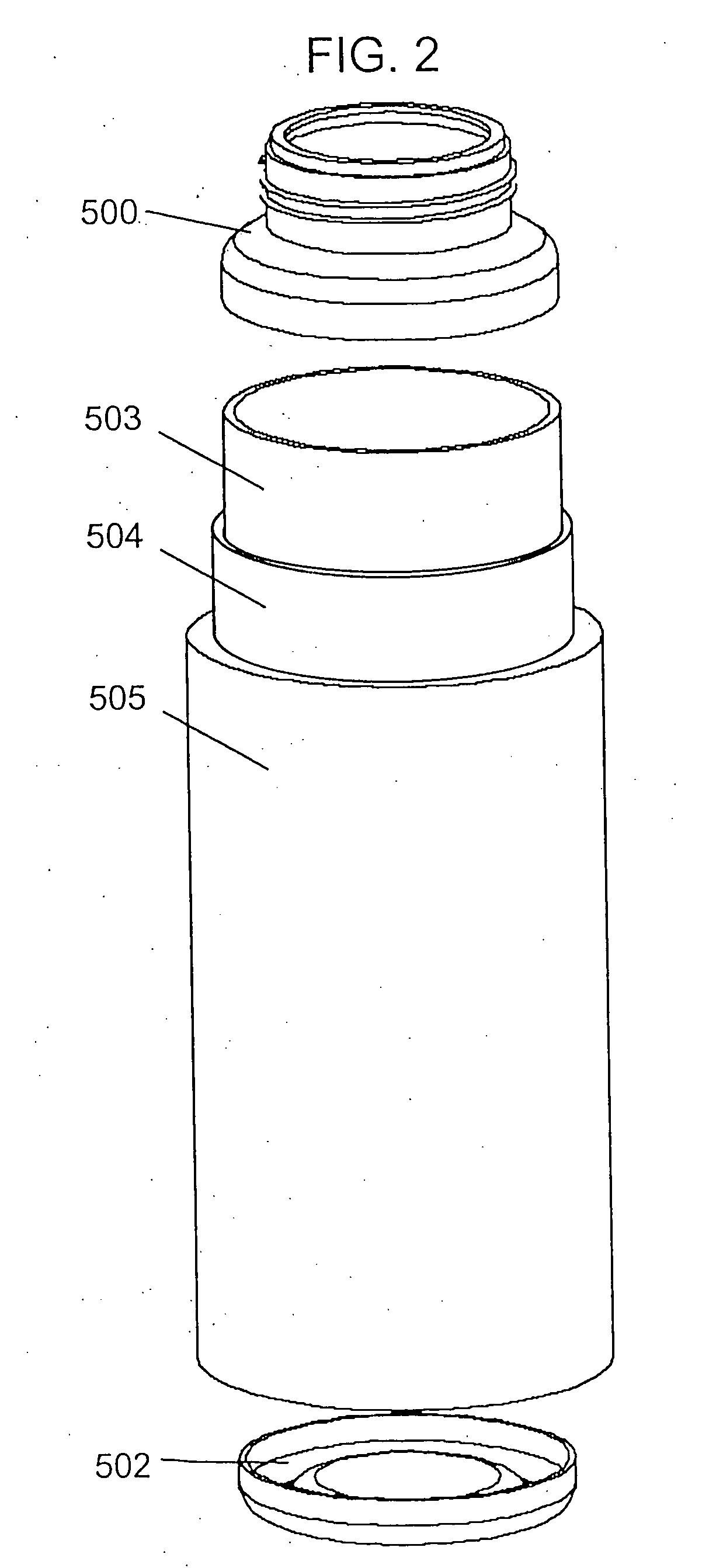
[0031] Disclosed herein are containers and enclosures that use pervaporative cooling to cool a liquid or item residing in such container or enclosure. In preferred embodiments, the containers are comprised of porous vent materials, also called porous matrices. In one embodiment, the container forms part of a pervaporatively-cooled garment. Porous matrices may be made of any of a wide variety of materials, including, but not limited to, plastics, elastomers, metals, glass, and ceramics. Combinations of plastics, elastomers, metals, glasses, or ceramics may also be used. The combinations may be intimate, such as from blending of two or more components to become co-sintered, or may be layered, such as from laminate structures derived from two or more materials. Combinations of different plastics, elastomers, metals, glasses, or ceramics can also be co-sintered or fabricated into laminate structures for use in pervaporative containers. Preferred plastics for porous vent materials includ...


PUM


Abstract

Disclosed are self-cooling pouches useful as containers for beverages and other liquids. Such pouches comprise a porous matrix as an element of the pouch body to effect the cooling of the pouch and a liquid contained therein by pervaporation of the liquid.

Description

RELATED APPLICATION DATA [0001] This application is a continuation of U.S. Ser. No. 10 / 1453,863 which claims priority under 35 U.S.C. §119(e) to U.S. Provisional Application Ser. No. 60 / 1388,609, filed Jun. 3, 2002, and which is also a continuation-in-part of U.S. Ser. No. 10 / 1162,119, filed Jun. 3, 2002, which is a continuation of U.S. Ser. No. 08 / 1933,639 filed Sep. 19, 1997, now US. Pat. No. 6,398,048.FIELD OF THE INVENTION [0002] This invention relates to a device and method of construction of a container or closure used to cool a liquid by means of pervaporation. BACKGROUND OF THE RELATED ART [0003] Evaporative cooling of both dwellings and water originated in Ancient Egypt and subsequently spread eastward through the Middle-East and Iran, to the north of India, westward across north Africa to southern Spain and other regions suffering from a hot and dry climate. In the initial use of this process non-glazed clay pots were used for centuries for the storage of water with the ad...

Claims


Application Information

Patent Timeline
Patent Type & Authority Applications(United States)
IPC IPC(8): F28C1/00F17C13/00A41D13/005A45F3/20A47G19/22A47G21/18A61J1/14A61J9/04B65D1/32B65D47/06B65D47/24B65D47/26B65D51/16B65D81/18B65D81/38F25D7/00F28D5/00
CPCA41D13/0053F28D5/00A45F3/18A45F3/20A47G19/2266A47G19/2272A47G21/18A47G2400/027A61J9/04A61M2207/00B65D1/323B65D47/06B65D47/242B65D47/265B65D51/1616B65D81/18B65D81/3886B65D2205/00F25D7/00F25D2331/803F25D2331/806F25D2331/808F25D2400/26A45F3/04
Inventor SMOLKO, DANIEL D.KEVORKIAN, GREGORY J.
Owner SMOLKO DANIEL D
Why Eureka
Try Eureka