Portable non-invasive ventilator with sensor

a non-invasive, sensor-based technology, applied in the direction of valves, respirators, mechanical devices, etc., can solve the problems of not fully automatic devices, need to be employed by skilled personnel,

Inactive Publication Date: 2006-11-09
CPAIR
View PDF10 Cites 59 Cited by
  • Summary
  • Abstract
  • Description
  • Claims
  • Application Information

AI Technical Summary

Problems solved by technology

A major problem with such devices, however, is that they need to be employed by skilled personnel in order to be effective.
Unfortunately, the devices contemplated by RE 38533 is not fully automatic in that the user must determine the nature of the distress condition for himself and then select the appropriate breathing mode.

Method used


Image

  • Portable non-invasive ventilator with sensor
  • Portable non-invasive ventilator with sensor

Examples


Embodiment Construction

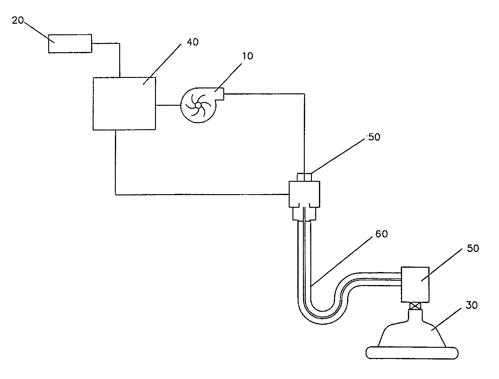
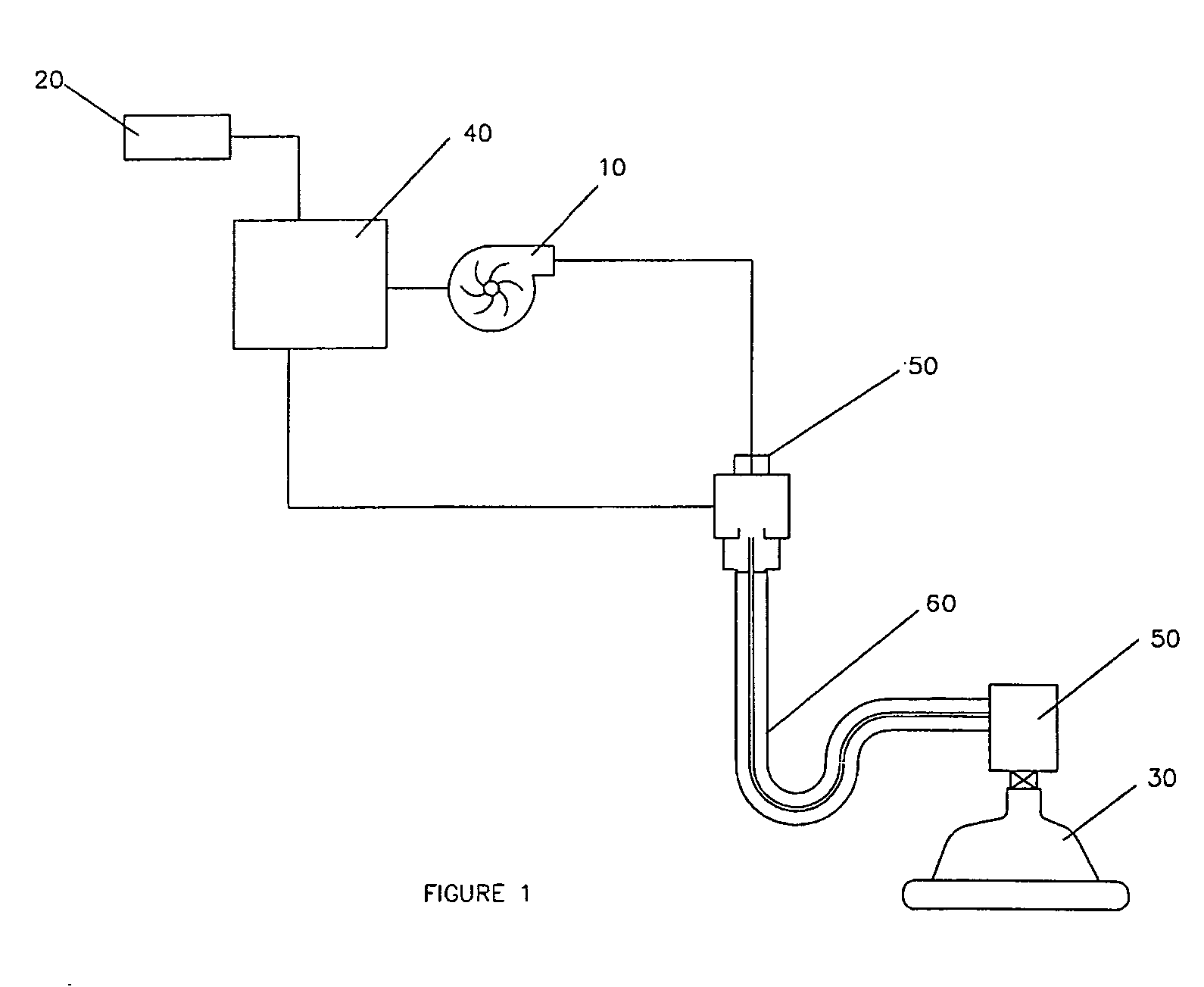
[0008] In FIG. 1 a ventilation system 1 generally includes a pressurized gas source 10; a portable power source 20; a face mask 30 coupled to the pressurized gas source 10; a microprocessor 40; a sensor 50 that provides information to the microprocessor to assist in automatically determining an appropriate breathing mode; and a circuitry 60 that utilizes the mask to deliver that mode.

[0009] The pressurized gas source 10 can be any of the myriad types known in the art, or later developed. Specifically contemplated is a limited drag turbine flow generator such as that described in U.S. Pat. No. 6,526,970. The gas source 10 shown in the figure pressurized atmospheric air, but could additionally or alternatively include a supply of gas having a higher content of oxygen than the ambient air.

[0010] The power source 20 can be any suitable power source, including for example a batter, super capacitor, hand carryable hydrogen fuel cell, and the like.

[0011] The face mask 30 can be any suit...


PUM


Abstract

A ventilator has a microprocessor that assists in automatically determining an appropriate breathing mode, and either the microprocessor or some other circuitry utilizes the mask to deliver that mode. Contemplated breathing modes include all of the recognized breathing modes (i.e, controlled mandatory ventilation, synchronized intermittent mandatory ventilation, pressure controlled and/or pressure supported ventilation, and high frequency ventilation) as well as other breathing modes.

Description

[0001] This application claims priority to U.S. provisional application Ser. No. 60 / 677529 filed May 3, 2005.FIELD OF THE INVENTION [0002] The field of the invention is breathing assistance devices. CL BACKGROUND P Numerous non-invasive ventilation devices have been developed over the years. Perhaps the simplest is a simple mask with compressible balloon bag commonly used by emergency medical personnel. A major problem with such devices, however, is that they need to be employed by skilled personnel in order to be effective. [0003] A few devices have been suggested that would provide a more automatic solution, and could therefore be more readily used by non-professionals. A recent example is that described in RE 38533. This, and all other referenced patents and applications are incorporated herein in their entirety. Unfortunately, the devices contemplated by RE 38533 is not fully automatic in that the user must determine the nature of the distress condition for himself and then sele...

Claims


Application Information

Patent Timeline
Patent Type & Authority Applications(United States)
IPC IPC(8): A61M16/00A62B7/04
CPCA61M16/0051A61M2016/0021A61M2016/0036A61M2205/3375A61M16/0069A61M2230/432A61M2230/435A62B18/006A61M2205/80A61M16/024
Inventor GAMBONE, ANTHONY
Owner CPAIR
Why Eureka
Try Eureka