Eureka AIR delivers breakthrough ideas for toughest innovation challenges, trusted by R&D personnel around the world.

Method of manufacturing liquid-jet head and liquid-jet head

Inactive Publication Date: 2006-11-09
SEIKO EPSON CORP
View PDF1 Cites 17 Cited by
  • Summary
  • Abstract
  • Description
  • Claims
  • Application Information

AI Technical Summary

Benefits of technology

[0010] With the aforementioned conditions taken into consideration, an object of the present invention is to provide a method of manufacturing a liquid-jet head, and a liquid-jet head, which make it possible to reliably prevent failure in ejection, such as the clogging of nozzles by extraneous matter.

Problems solved by technology

However, when the penetrating portion is formed by means of such a mechanical process, extraneous matter such as scraps is produced, and the extraneous matter goes into passages such as the pressure generating chambers.
As a result, the mechanical process brings about a problem that the extraneous matter presents a cause of failure in ejection.
Incidentally, if the penetrating portion is caused to undergo, for example, a cleaning process or the like immediately after the penetrating portion is formed, extraneous matter such as scraps can be removed to some extent, but it is still difficult to remove the extraneous matter completely.
In addition, the mechanical process of forming the penetrating portion produces cracks and the like around the penetrating portion.
This also brings about a problem that the production of cracks causes failure in ejection.
Specifically, if ink is filled and ejected from the nozzle orifices while such cracks are left as they are, fragments are detached from cracked parts, these fragments clog up nozzle orifices.
As a result, the mechanical process brings about a problem that the clogging causes failure in ejection.
Adoption of this structure may check extraneous matter from being produced to some extent, but it is still difficult to completely prevent failure in ejection from stemming from the extraneous matter.
In addition, the part of the protection film which has been formed on the top of the coating film made of a resin material is poor at adhesion to a resin material, and accordingly is easy to come off from the coating film.
Part of the protection film which has come off from the coating film is likely to clog up nozzles or cause similar problems.
It goes without saying that such problems also occur in a method of manufacturing other liquid-jet head which eject liquids other than ink.

Method used


Image

  • Method of manufacturing liquid-jet head and liquid-jet head
  • Method of manufacturing liquid-jet head and liquid-jet head
  • Method of manufacturing liquid-jet head and liquid-jet head

Examples


embodiment 1

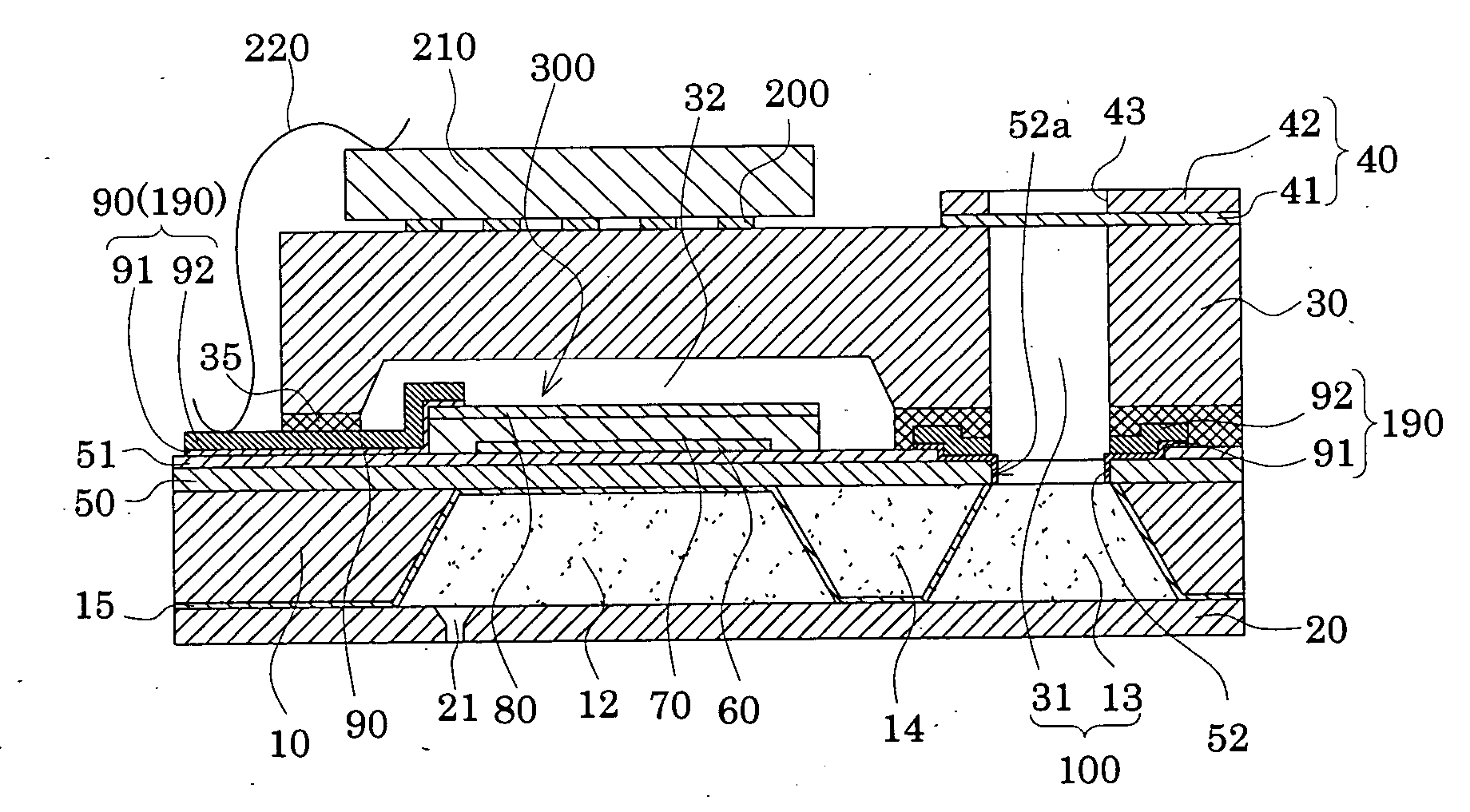
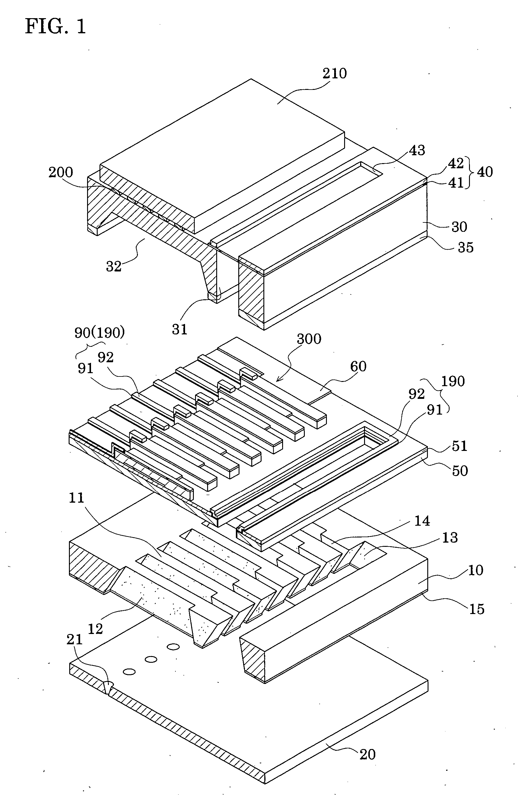
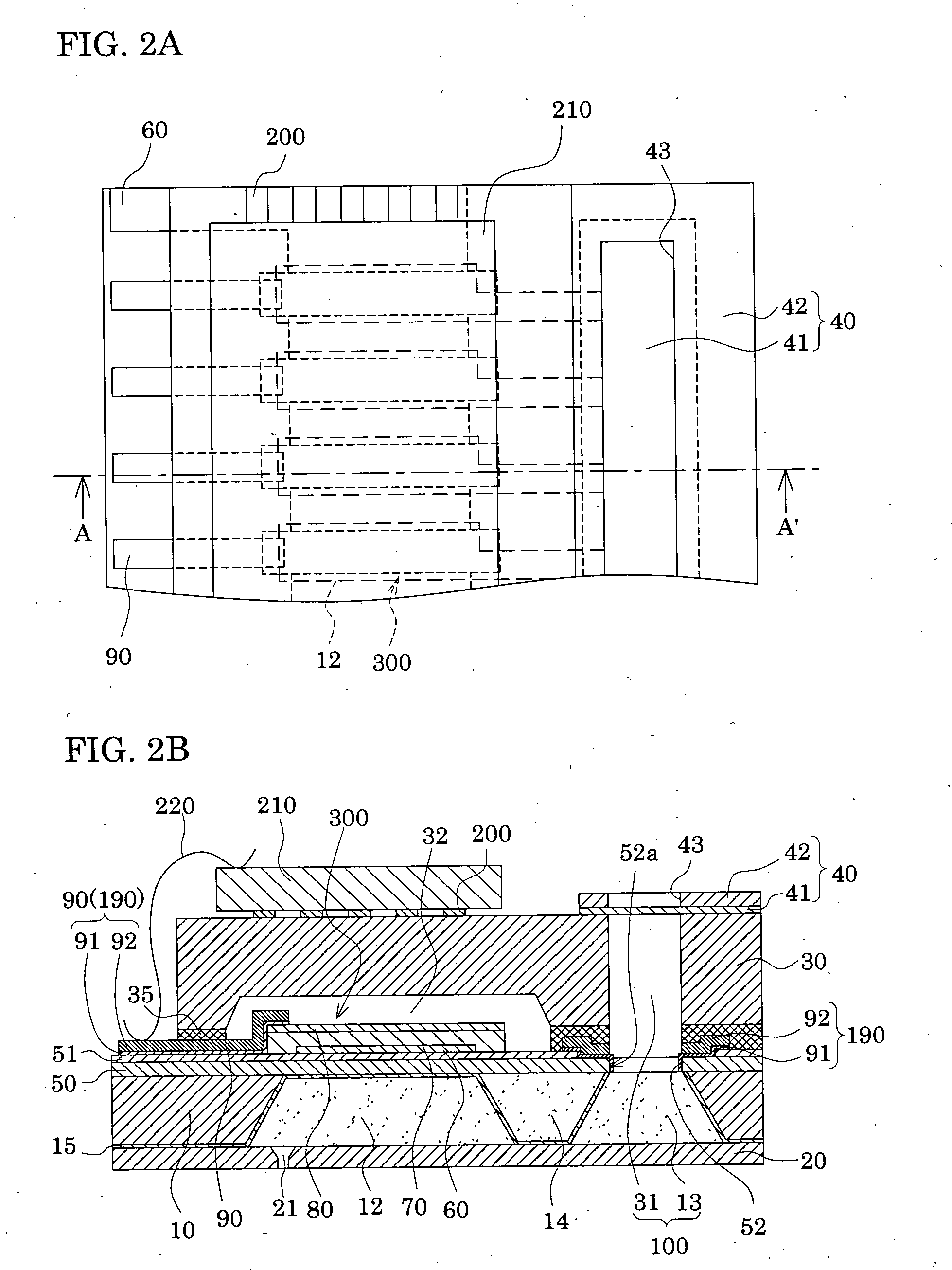
[0048]FIG. 1 is an exploded perspective view of an inkjet recording head to be manufactured by means of a manufacturing method according to Embodiment 1 of the present invention. FIGS. 2A and 2B are respectively a plan view of, and a cross-sectional view of, the inkjet recording head shown in FIG. 1. A passage-forming substrate 10 is made of a single crystal silicon substrate in which silicon crystals on the face surface are in the (110) plane direction. As illustrated, an elastic film 50 made of silicon dioxide is formed beforehand on one surface of the passage-forming substrate by thermal oxidation. The elastic film 50 has a thickness of 0.5 to 2 μm.

[0049] In the passage-forming substrate 10, a plurality of pressure generating chambers 12 are provided side-by-side in the width direction of the passage-forming substrate 10. In addition, a communicating portion 13 is formed in an area outside of the pressure generating chambers 12 in the longitudinal direction in the passage-formin...


PUM

PropertyMeasurementUnit
Thicknessaaaaaaaaaa
Angleaaaaaaaaaa
Electrical resistanceaaaaaaaaaa

Abstract

Included are the steps of: forming piezoelectric elements on a surface of a passage-forming substrate with a vibration plate in between, and forming a penetrating portion by removing an area in the vibration plate, which area will serve as a communicating portion; forming lead electrodes and sealing up the penetrating portion with an interconnect layer; joining a reservoir forming plate to a surface of a passage-forming substrate; forming liquid passages by wet-etching; forming protection films on inner surfaces of the liquid passages; detaching and removing a protection film on an interconnect layer; and causing a reservoir portion and a communicating portion to communicate with each other by removing a corresponding part of the interconnect layer, and in accordance with the manufacturing method, while the liquid passages are being formed, the communicating portion is formed in a way that an edge of an opening of the vibration plate is located outside an edge of an opening which is close to the penetrating portion, and in a way that at least the edge of the opening of the penetrating portion is thus configured of only any one of the vibration plate and the interconnect layer.

Description

[0001] The entire disclosure of Japanese Patent Application Nos. 2005-099705 filed Mar. 30, 2005 and 2005-334954 filed Nov. 18, 2005 is expressly incorporated by reference herein. BACKGROUND OF THE INVENTION [0002] 1. Field of the Invention [0003] The present invention relates to a method of manufacturing a liquid-jet head, and to a liquid-jet head. Specifically, the present invention relates to a method of manufacturing an inkjet recording head which ejects ink as a liquid, and to a liquid-jet head. [0004] 2. Description of the Prior Art [0005] An inkjet recording head with the following configuration is among inkjet recording heads which are used as liquid-jet heads (see Japanese Patent Laid-open Official Gazette No. 2003-159801, for example). Such an inkjet recording head includes a passage-forming substrate, piezoelectric elements and a reservoir forming plate. In the passage-forming substrate, pressure generating chambers and a communicating portion are formed. The pressure gen...

Claims


Application Information

Patent Timeline
IPC IPC(8): B41J2/045B41J2/055B41J2/135B41J2/14B41J2/145B41J2/16
CPCB41J2/14233B41J2/161B41J2/1629Y10T29/42B41J2002/14241Y10T29/49401B41J2002/14491
Inventor MATSUZAWA, AKIRAOTA, MUTSUHIKO
Owner SEIKO EPSON CORP
Why Eureka
Eureka Blog
Learn More