Backlight structure

a backlight and structure technology, applied in the field of backlight structure, can solve the problems of deteriorating light efficiency and increasing manufacturing costs, and achieve the effect of increasing the light output surfa

Inactive Publication Date: 2006-11-09
AU OPTRONICS CORP
View PDF5 Cites 11 Cited by
  • Summary
  • Abstract
  • Description
  • Claims
  • Application Information

AI Technical Summary

Benefits of technology

[0008] It is therefore an object of the invention to provide a backlight structure having a light guide with a cantilever structure. The area of the light outputting surface on the light guide is equal to the sum of the area of the light guide body and the area of the cantilever. Compared with the conventional light guide without having a cantilever structure, the light guide of the invention increases a larger light outputting surface by the light-emitting, area of the cantilever.

Problems solved by technology

Despite this backlight structure is capable of effectively enlarge the display area of the light outputting surface, the light efficiency is deteriorated because the light must pass through the light-mixing plate first and then enter the light guide.
The manufacturing cost is increased due to an additional manufacturing process of the disposition of the light-mixing plate.

Method used


Image

  • Backlight structure
  • Backlight structure
  • Backlight structure

Examples


first embodiment

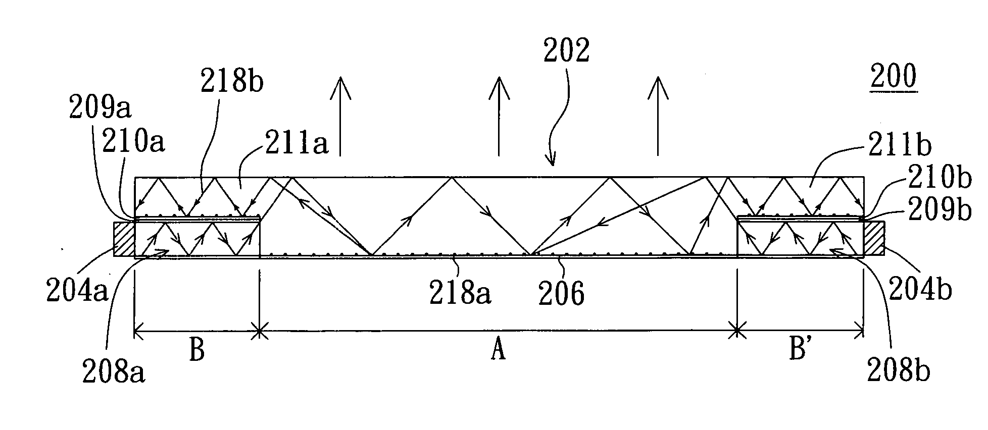
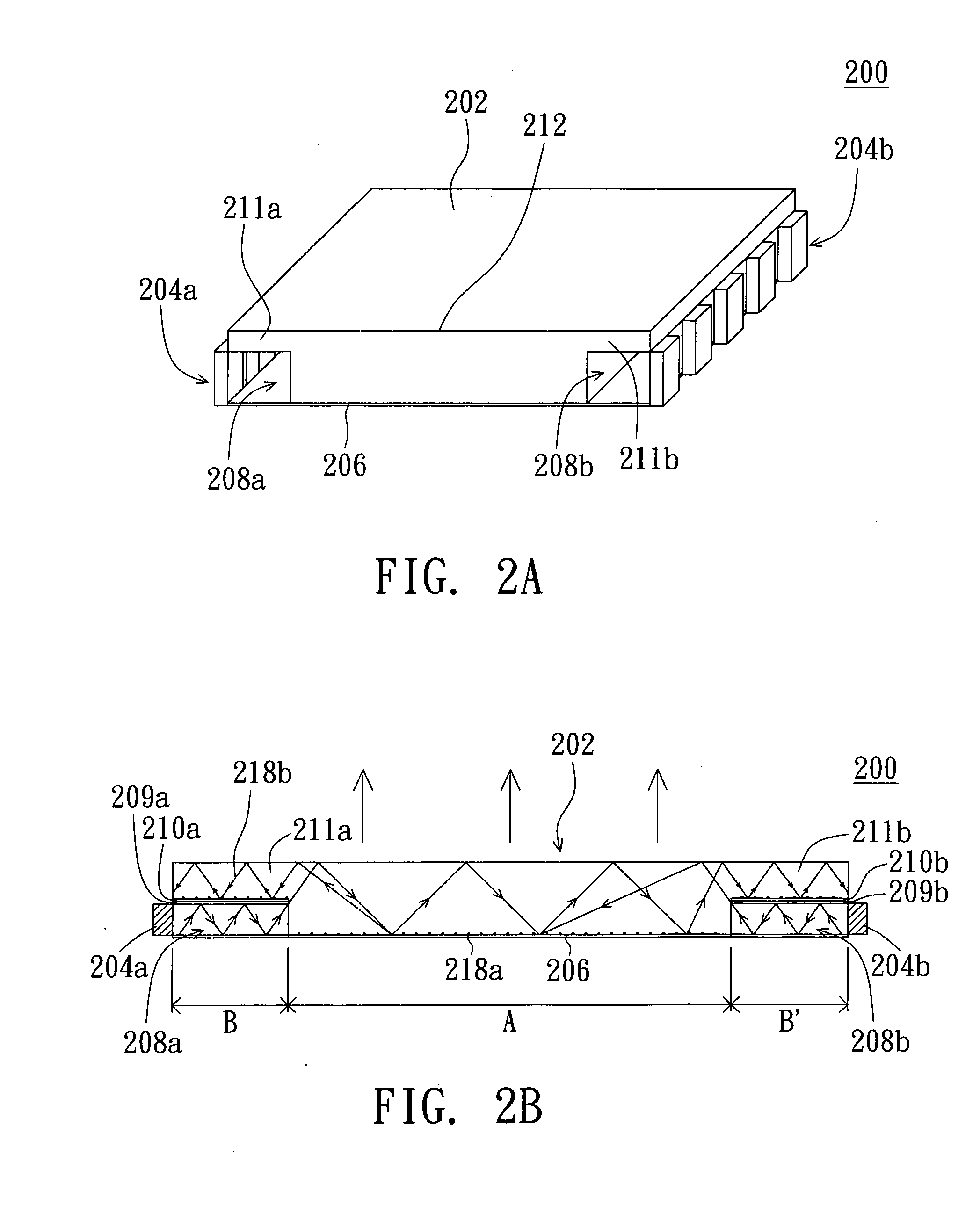
[0017] Referring to FIG. 2A, a three-dimensional diagram of the backlight structure according to a first embodiment of the invention is shown. The backlight structure 200 applied in an LCD includes a light guide 202, a first reflector 206, a first light source module 204a and a second light source module 204b. The light guide 202 has a first groove 208a and a second groove 208b respectively positioned on two sides of the bottom of the light guide 202. The first reflector 206 is disposed below the light guide 202 and extended to the first groove 208a and the second groove 208b for a first light mixing zone and a second light mixing zone to be formed on the first groove 208a and the second groove 208b, respectively. A first cantilever 211a and a second cantilever 211b are respectively formed above the first groove 208a and the second groove 208b but below the top surface 212 of the light guide 202.

[0018] Referring to both FIG. 2A and FIG. 2B, FIG. 2B is a side view of the backlight s...

second embodiment

[0019] Referring to FIG. 3, a side view of the backlight structure according to a second embodiment of the invention is shown. The backlight structure has a first light source module 304a and a second light source module 304b. The present embodiment differs with the first embodiment in that the bottom surface 317 of the first cantilever 311a and that of the second cantilever 311b of the backlight structure 300 respectively are a bevel so as to achieve to achieve the same effect with the first embodiment. In the present embodiment, the disposition of the cantilever dot patterns is optional. The disposition of the cantilever dot patterns enables the light evenly distributed on the bevel to be emitted. In the absence of the disposition of the cantilever dot patterns, the light evenly distributed on the bevel can be emitted by adjusting the slope of the bevel.

third embodiment

[0020] Referring to FIG. 4, a side view of the backlight structure according to a third embodiment of the invention is shown. The present embodiment differs with the first embodiment and the second embodiment in that the backlight structure 400 of the third embodiment only has a cantilever 411 disposed on the light guide 402. The present embodiment has the first light source module 404 disposed on one side or two sides of the backlight structure and mix the light in the first groove 408. After the mixed light enters the light guide 402, the evenly distributed light is emitted from the light guide 402.


PUM

PropertyMeasurementUnit
contained angleaaaaaaaaaa
areaaaaaaaaaaa
light-mixing distanceaaaaaaaaaa

Abstract

A backlight structure is provided. The backlight structure includes a light guide, a light source module and a reflector. The light guide has a groove which is positioned on one side of the bottom of the light guide. The reflector is disposed below the light guide and extended to the groove for a light mixing zone to be formed in the groove. The light source module corresponds to the groove.

Description

[0001] This application claims the benefit of Taiwan application Serial No. 94114456, filed May 4, 2005, the subject matter of which is incorporated herein by reference. BACKGROUND OF THE INVENTION [0002] 1. Field of the Invention [0003] The invention relates in general to a backlight structure, and more particularly to a backlight structure applied in a liquid crystal display (LCD). [0004] 2. Description of the Related Art [0005] Referring to FIG. 1, a light-mixing diagram of a conventional backlight structure is shown. In side type backlight structure 100 applied in the LCD, the backlight source module is normally formed by a number of light sources. For example, a light source 8, a light source 9 and a light source 10 form the light source module. The light source can be a red light emitting diode (LED), the light source 8 can be a red LED, the light source 9 can be a green LED, and light source 10 can be a blue LED. The light emitted from a light outputting surface 7 of light gu...

Claims


Application Information

Patent Timeline
Patent Type & Authority Applications(United States)
IPC IPC(8): G02F1/1335
CPCG02B6/002G02B6/0068G02B6/0055
Inventor LIU, PANG-HSUANKAO, KO-CHIA
Owner AU OPTRONICS CORP
Why Eureka
Try Eureka