Flat light source

a light source and flat technology, applied in the field of flat light sources, can solve the problems of reducing incidence efficiency, reducing display quality, and reducing display quality, and achieve the effect of preventing the reduction of incidence efficiency and the degradation of display quality

Inactive Publication Date: 2009-06-09
MITSUBISHI ELECTRIC CORP
View PDF18 Cites 9 Cited by
  • Summary
  • Abstract
  • Description
  • Claims
  • Application Information

AI Technical Summary

Benefits of technology

[0012]An object of the present invention is to provide a flat light source achieving easy construction while preventing decrease in incidence efficiency and degradation in display quality due to a displacement of a light emitting region of each point light source from a light incident surface of a light guide plate, with each point light source disposed such that a light emitting surface thereof is in contact with the light incident surface of the light guide plate.
[0014]The first overhang is in contact with the light outgoing surface with each point light source provided such that the light emitting surface faces the light incident surface, which prevents a displacement of each point light source and the light guide plate from each other due to warpage of the light guide plate, and allows most of the light emitted from each point light source to enter the light incident surface of the light guide plate. Accordingly, light emitted from each point light source is used effectively to prevent degradation in luminance of the flat light source and fluctuations in luminance in the light outgoing surface.

Problems solved by technology

In contrast, when warpage occurs in the light guide plate, the light emitting region of each point light source is displaced from the light incident surface of the light guide plate, resulting in decreased incidence efficiency and degraded display quality.
With such construction, however, problems of decreased incidence efficiency and degraded display quality still arise when the light emitting region of each point light source is displaced from the light incident surface of the light guide plate.
Further, the enclosure needs to have rigidity to compensate for warpage of the light guide plate, which causes problems of size increase of the liquid crystal display apparatus and construction difficulty.
Furthermore, when engaging the light guide plate with the enclosure, they rub against each other to generate foreign matters, which results in display failure.

Method used


Image

  • Flat light source
  • Flat light source
  • Flat light source

Examples


Embodiment Construction

A. First Preferred Embodiment

A-1. Device Construction

[0032]A flat light source according to a first preferred embodiment of the present invention will be described with reference to FIGS. 1 through 14.

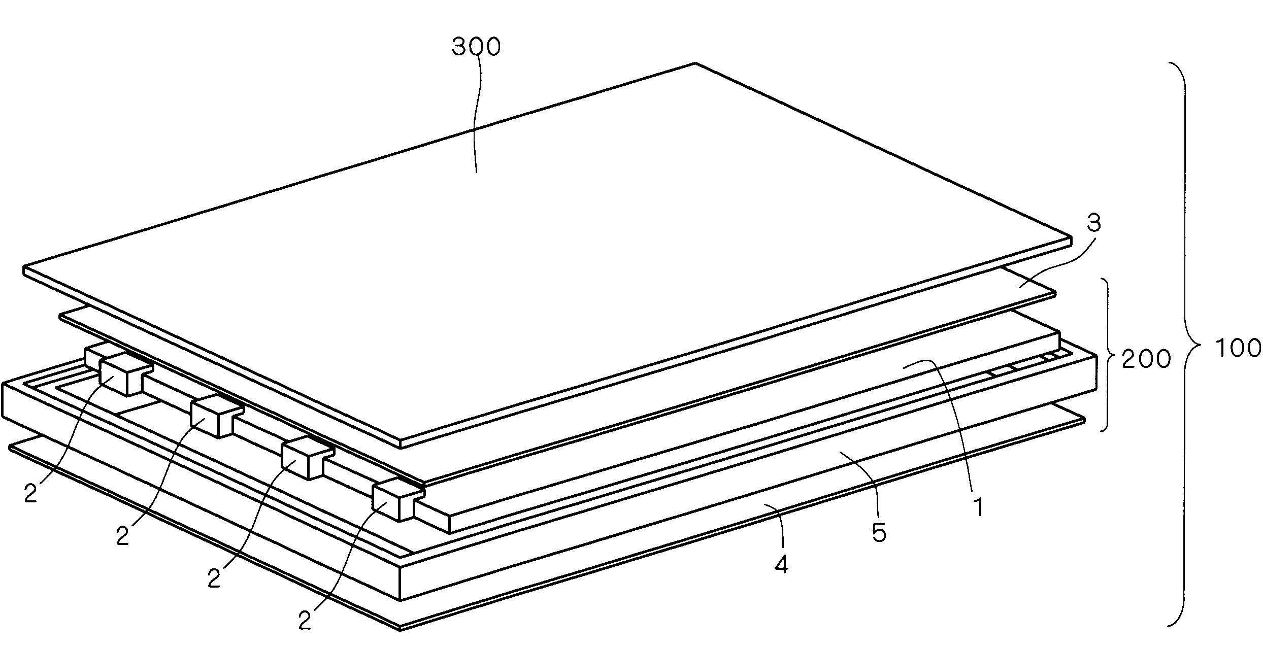
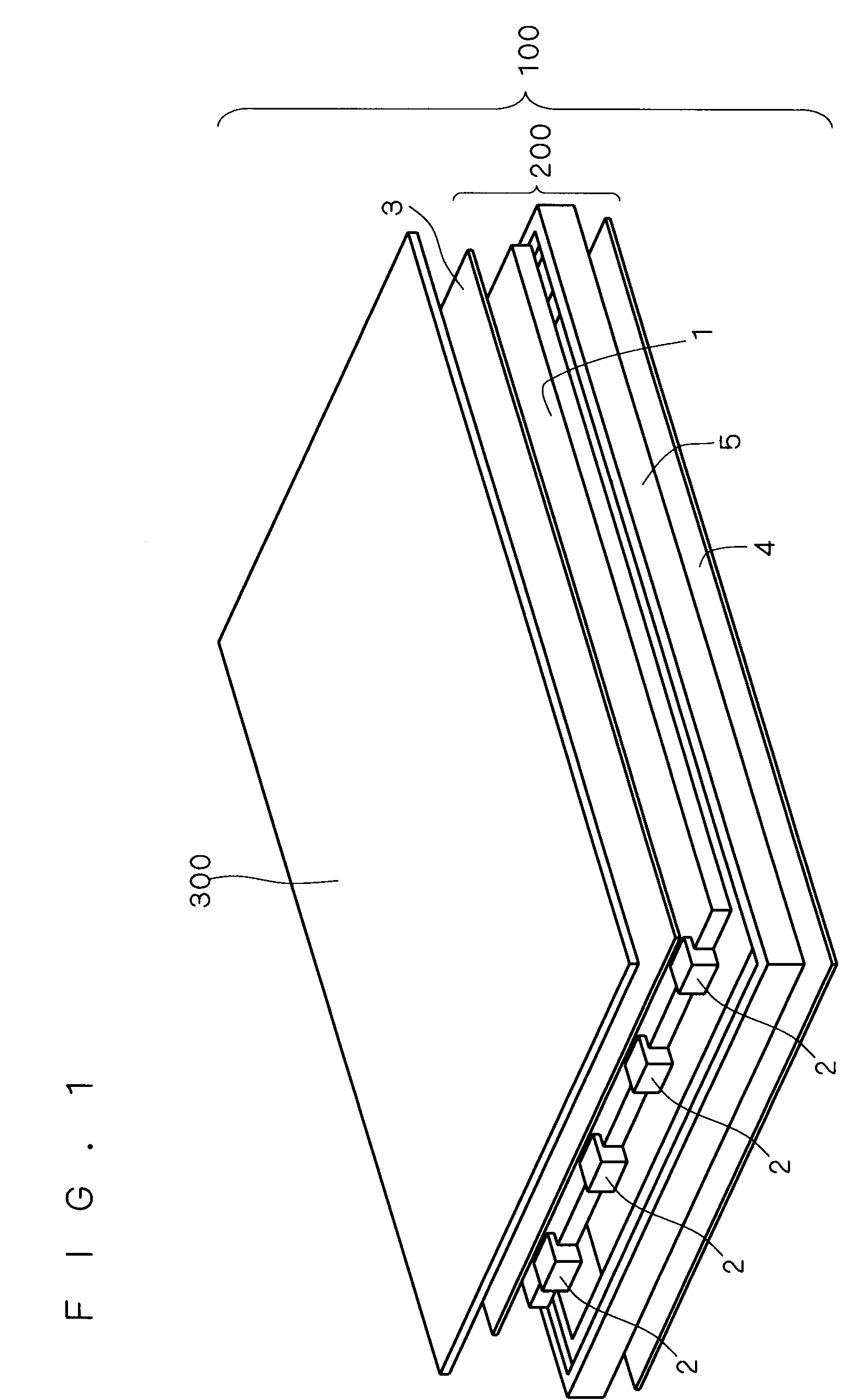
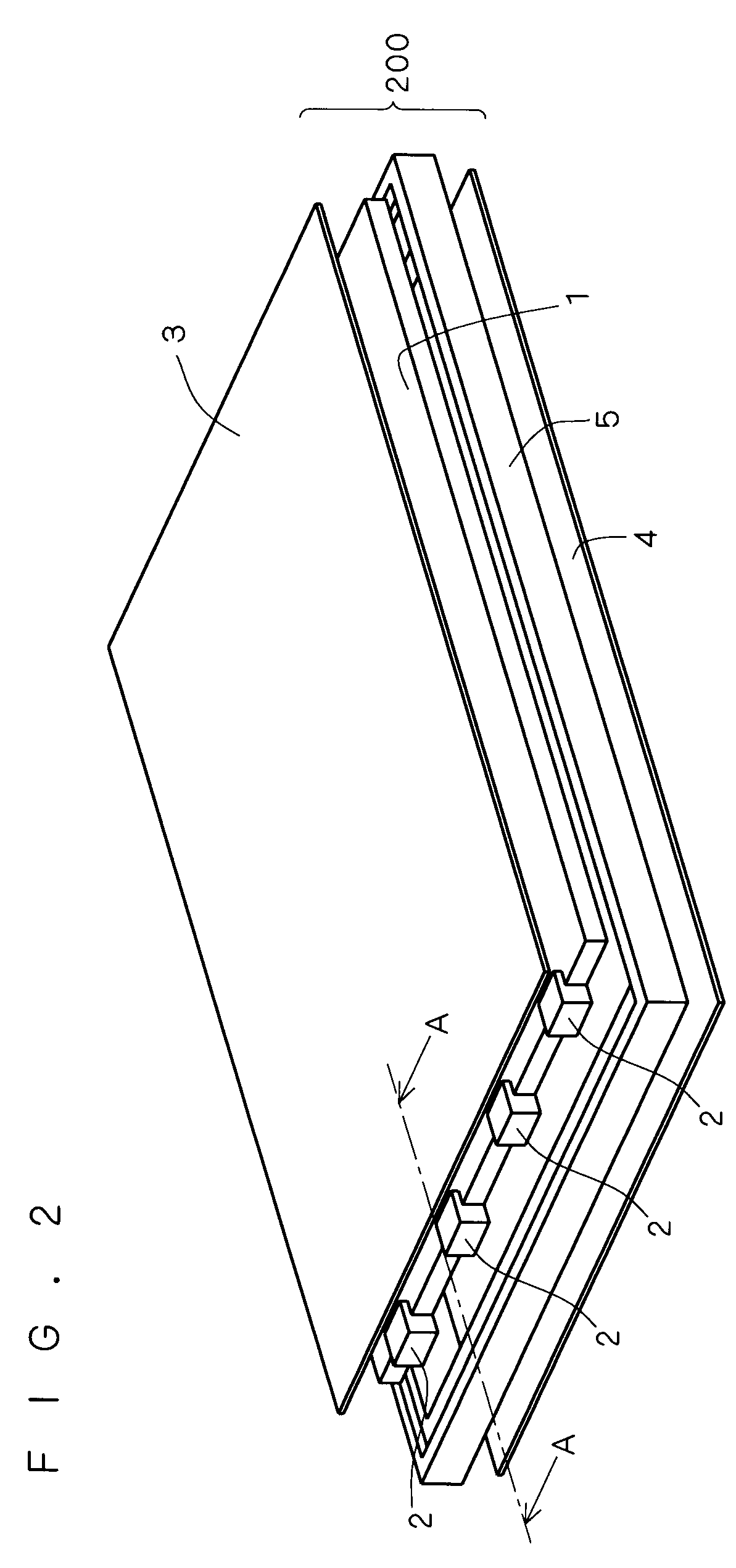
[0033]FIG. 1 is a perspective view showing the construction of a liquid crystal display apparatus 100 provided with a flat light source 200 according to the present embodiment. FIG. 2 is a perspective view showing the construction of the flat light source 200, and FIG. 3 is a sectional view showing the flat light source 200 viewed in the direction of the arrow A.

[0034]As shown in FIG. 1, the liquid crystal display apparatus 100 is provided with a liquid crystal panel 300 and the flat light source 200 disposed on the rear surface of the liquid crystal panel 300.

[0035]The flat light source 200 includes a light guide plate 1, a plurality of point light sources 2 attached to at least one side surface of the four side surfaces of the light guide plate 1, an enclosure 5 for storing the light...


PUM


Abstract

Each point light source includes an overhang projecting perpendicularly to a light emitting surface from one side of the light emitting surface, and the overhang has its main surface made in contact with a light outgoing surface of a light guide plate with the light emitting surface facing a light incident surface of the light guide plate. Engagement of the overhang with the light outgoing surface of the light guide plate prevents a displacement of the light emitting surface of the point light source and the light incident surface of the light guide plate even when the light guide plate suffers from deformation such as warpage. Even if a displacement occurs, the presence of the overhang reflects leaked light to guide it to the light incident surface of the light guide plate.

Description

FIELD OF THE INVENTION[0001]The present invention relates to a flat light source, and more particularly to a flat light source for use in a liquid crystal display apparatus.DESCRIPTION OF THE BACKGROUND ART[0002]A typical liquid crystal display apparatus includes a liquid crystal panel and a flat light source, which is provided on the rear surface of the liquid crystal panel. The flat light source includes the sidelight type and the direct-light type depending on how the light source is disposed.[0003]A flat light source of the sidelight type (also called edge-light type) has its light sources disposed in a crystal liquid display near the side surface of the liquid crystal display apparatus, while a flat light source of the direct-light type has its light sources disposed to face the rear surface of the liquid crystal panel.[0004]There is a sidelight type flat light source employing a light guide plate which receives light from the light sources and diffuses the light therein to sup...

Claims


Application Information

Patent Timeline
Patent Type & Authority Patents(United States)
IPC IPC(8): F21V7/04
CPCG02B6/0031G02B6/0091G02F1/1335
Inventor KIYOHARA, TORUYONEDA, TOSHIYUKI
Owner MITSUBISHI ELECTRIC CORP
Why Eureka
Try Eureka