Heatsink method and apparatus

Inactive Publication Date: 2006-11-09
GLT ACQUISITION
View PDF33 Cites 56 Cited by
  • Summary
  • Abstract
  • Description
  • Claims
  • Application Information

AI Technical Summary

Benefits of technology

[0012] The invention relates to a heatsink. More particularly, the invention relates to a heatsink having a expanding or tapered geometry that improves cooling efficiency. A tapered geometry between heatsink heat dissipation elements, as a function of distance along a z-axis opposing gravity, decreases resistance to rarificati

Problems solved by technology

Electronic devices continue to generate more and more heat while the overall dimension

Method used


Image

  • Heatsink method and apparatus
  • Heatsink method and apparatus
  • Heatsink method and apparatus

Examples


example i

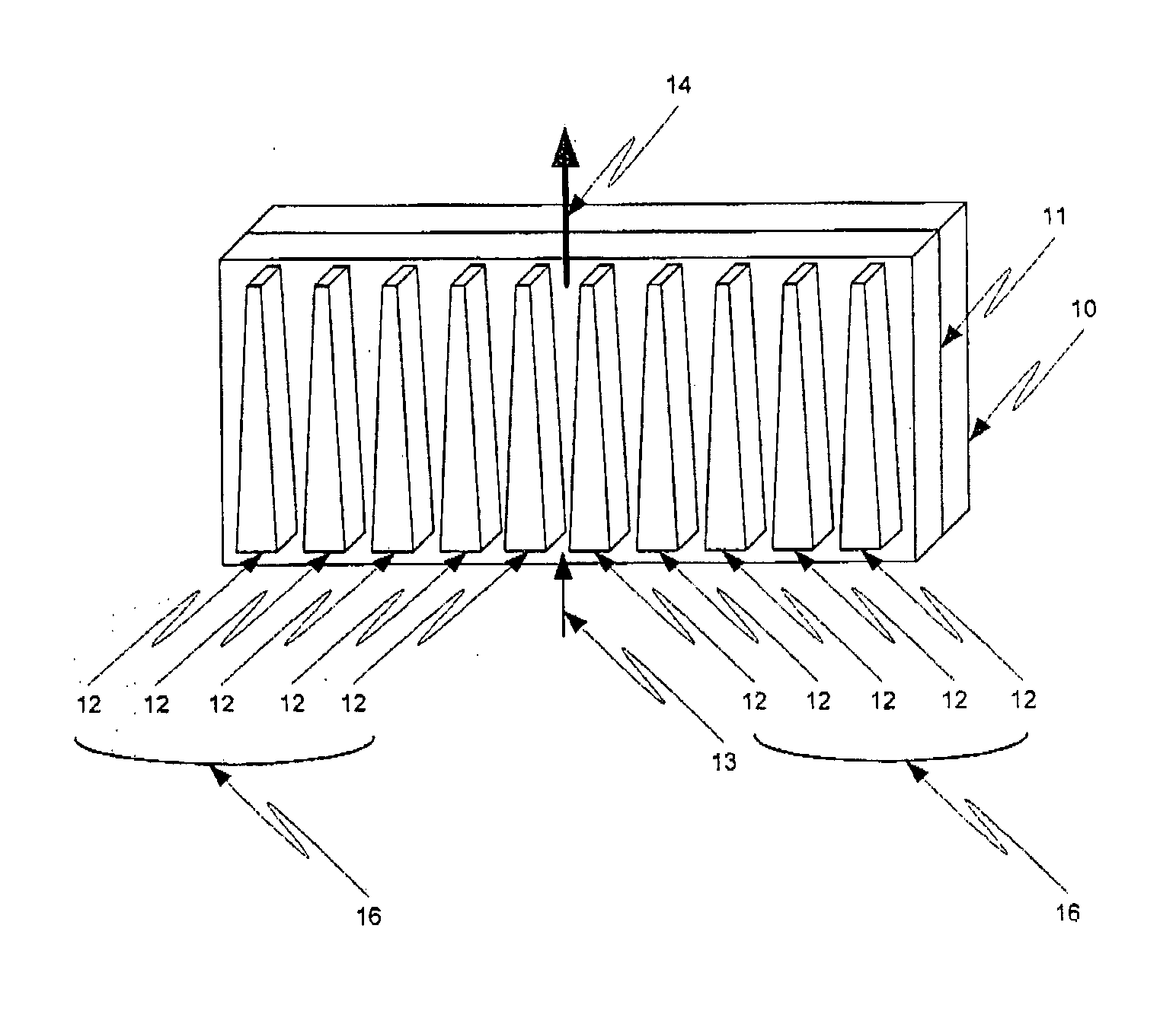
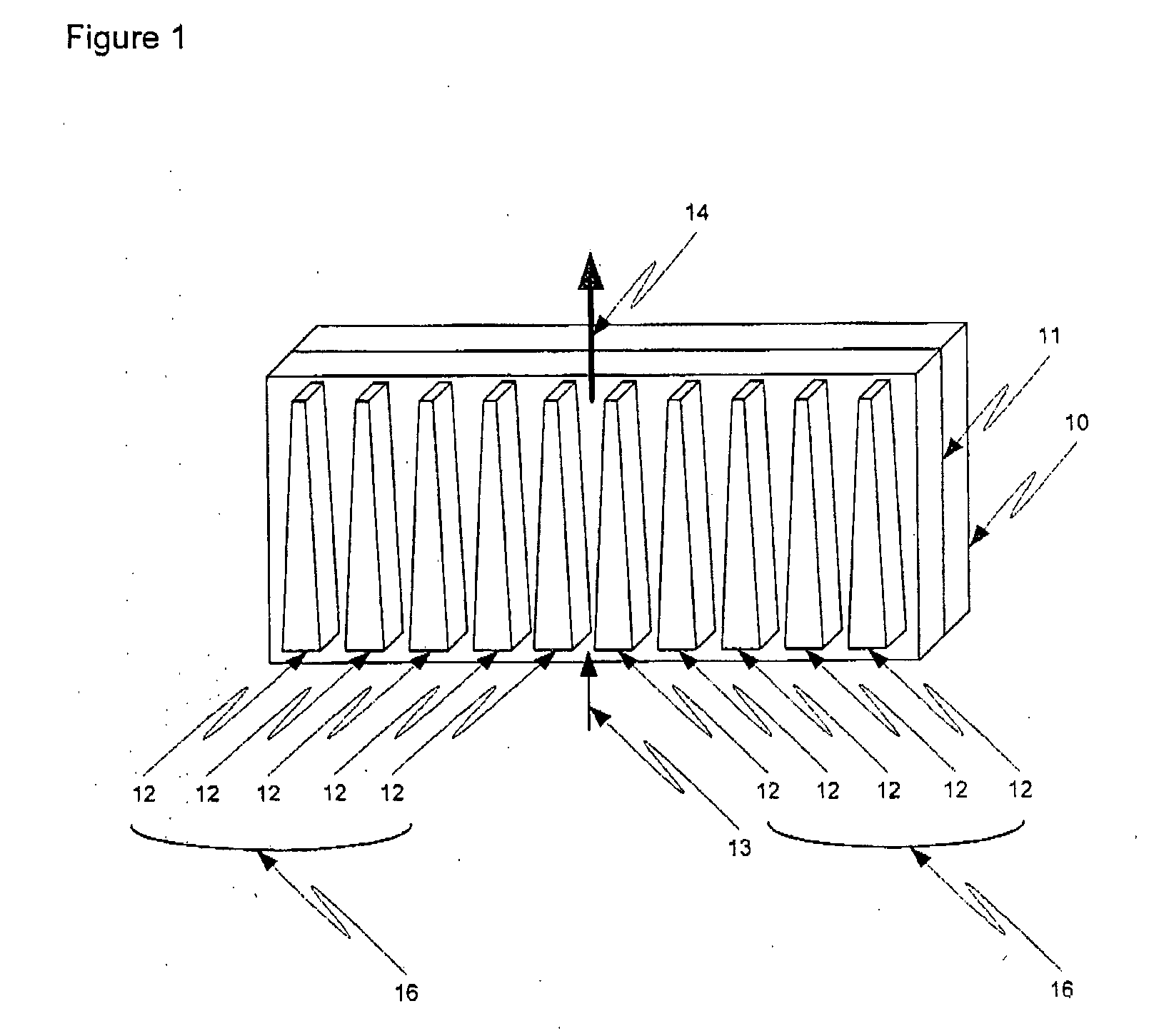
[0030] In a first example of the invention, a heatsink is coupled to a heat source. FIG. 1 provides a perspective view of a heatsink 11 coupled to a heat source 10. In a first case, the heatsink 11 is attached to at least a portion of one side of the heat source 10. In a second case, the heatsink 11 surrounds the heat source 10 or covers a plurality of sides of the heat source 10. The heatsink has a set of heat exchange elements 16, such as a series of fins 12. The fins 12 are either attached to the heatsink 11 or are integral to the heatsink 11. The area, distance, or volume between two or more fins 12 is referred to in a number of ways including: a gap, a channel, a distance between heat dissipating elements, a region between fins, a cross-sectional area, a region between a pair of fins, and an expanding volume along the z-axis. By tapering the fins 12, the distance between the fins 12 increases as a function of height. In this example, a gas, such as air, passively moves either t...

example ii

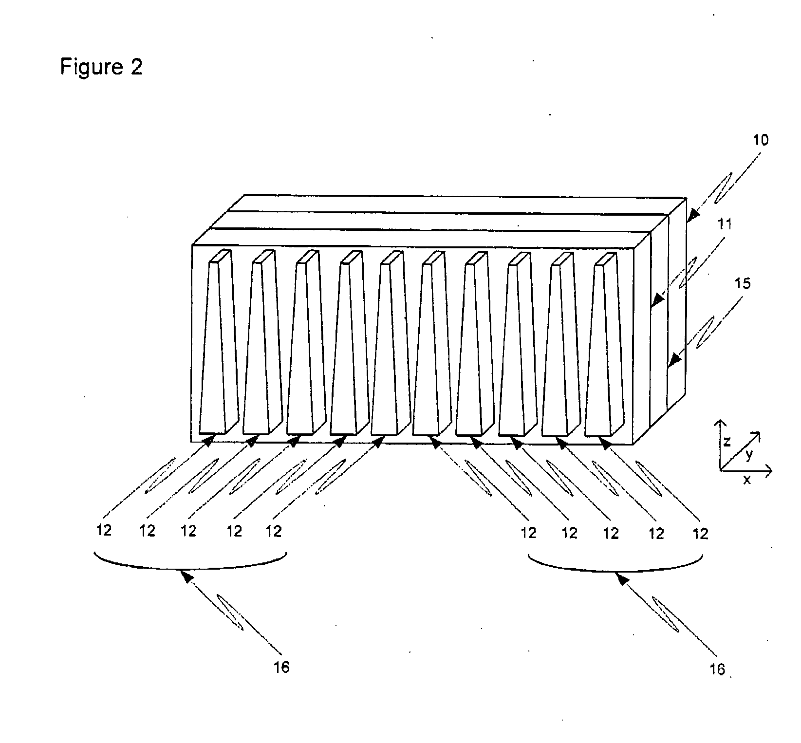
[0032] A second example of the invention is presented schematically in FIG. 2. A heat source 10 is coupled to a heatsink 11 through intermediate means 15, such as a thermally conductive material or a heatpipe. The intermediate means is optionally a layer. The intermediate means 15 are designed to move heat from the heat source 10 to the heatsink 11. The intermediate means cover at least part of the heat source 10 and the heatsink 11 covers at least part of the intermediate layer. Optionally, two, three, or more intermediate means or materials are used. The heatsink is preferably constructed with a set of two or more heat exchange elements, such as a set of fins 12, designed to induce and increase air flow across the heatsink passively.

example iii

[0033]FIG. 3 illustrates a third example of the invention. In this example, a heatsink 11 covers, directly or indirectly, at least a portion of a surface of a preferably vertically orientated heat source 10. A set of heat exchange elements, illustrated as fins 12 are integrated into the heatsink 11 are tapered in two-dimensions. The distance between the fins 12 is tapered along the z-axis as in Example I. In addition, the fins 12 are tapered between the outmost surface of the fin and the contact with the heatsink 11. This allows the gas to expand and rise upward with a component vector toward the heatsink 11. This results in a larger airflow and more contact area with the base portion of the heatsink 11, which is typically hotter than the outermost portion of the fins 12. Thus, tapering the fins in at least-two dimensions increases the efficiency of the heatsink. Optionally, the heat dissipating element, such as a cone or fin, is tapered along three-dimensions. In addition, tapering...


PUM


Abstract

The invention relates to a heatsink. More particularly, the invention relates to a heatsink having tapered geometry that improves passive cooling efficiency. A tapered geometry between heatsink heat dissipation elements, as a function of distance along a z-axis opposing gravity, decreases resistance to rarification of passively flowing cooling gas upon heating. Thus, the tapered heatsink elements result in higher velocity of gas flow and increased cooling efficiency of the heatsink. Optionally, the heatsink is made from a thermally conductive polymer allowing the heatsink to be created in complex shapes using injection molding.

Description

CROSS REFERENCE TO RELATED APPLICATION [0001] This application claims priority to U.S. provisional patent application Ser. No. 60 / 678,433, filed May 5, 2005, which is incorporated herein in its entirety by this reference thereto.BACKGROUND OF THE INVENTION [0002] 1. Field of the Invention [0003] The invention relates to a heatsink. More particularly, the invention relates to a heatsink having a novel geometric shape that improves cooling efficiency. Optionally, the heatsink is made from a thermally conductive polymer allowing the heatsink to be created in complex shapes using injection molding. [0004] 2. Description of Related Art [0005] Heatsink [0006] K. McCullough, Net-shape molded heat exchanger, U.S. Pat. No. 6,397,941 (Jun. 4, 2002) describes a heat exchange having a thermally conductive main body having a number of thermally conductive arms or heat pipes extending from the main body and thermally conductive fins coupled to the arms or pipes. [0007] S. Barsun, Heatsink with mu...

Claims


Application Information

Patent Timeline
IPC IPC(8): H05K7/20
CPCF28F3/02F28F13/08H01L23/3737H01L23/467H01L2924/0002H01L2924/00
Inventor ABUL-HAJ, ROXANNE E.ABUL-HAJ, N. ALANSTIPPICK, TIMOTHY W.HAZEN, KEVIN H.
Owner GLT ACQUISITION
Why Eureka
Try Eureka