
Shaker with reciprocating agitator

a technology of agitator and shaker, which is applied in the field of shaker, can solve the problems of insufficient movement or reach of the agitator, cracks and crevices, and difficult cleaning, and achieve the effects of adequate internal container coverage, full utilization, and maximum shaking efficiency

Active Publication Date: 2006-11-09
RUNWAY BLUE LLC
View PDF22 Cites 37 Cited by
  • Summary
  • Abstract
  • Description
  • Claims
  • Application Information

AI Technical Summary

Benefits of technology

The present invention is a shaker with an agitator that maximizes shaking efficiency by providing both adequate internal container coverage and full utilization of spring agitating capacity. The shaker has a mixing vessel with a guide rod and a hollow agitator frame that operatively reciprocates from one end of the vessel to the opposite end to mix fluid contained within the vessel. The agitator frame can slide onto and off of the guide rod and has an internal attachment member that operatively attaches the frame to the guide rod and slides along the guide rod. The agitator frame has concentric coils that make up the external mixing member and the internal attachment member, which are made from one continuous piece of material. The guide rod is substantially solid. The agitator frame has a primary axis of elast cty parallel with the guide rod and along which the frame contracts when it hits one of the vessel ends. The agitator frame has a spring that operatively impacts the vessel's ends only at its ends. The technical effects of the invention are improved shaking efficiency, better mixing of fluids, and easier handling of the shaker.

Problems solved by technology

These attached elements often create cracks and crevices, however, which are difficult to clean.
Furthermore, these devices often do not allow sufficient movement or reach of the agitator to the entire container area, and thus fail to provide optimal mixing.
Hand mixing the above-mentioned mixtures into a smooth, homogeneous suspension often requires a considerable amount of work as well.
These agitators strike the container walls in random directions with respect to their direction of compressibility, however, and thereby fail on most such contacts to compress.
Hence the prior art fails to provide an agitation element and mixture vessel combination that is effective at reaching clumps and aggregation at the top, middle and bottom of a container while utilizing the full agitating capacity of the agitator.

Method used


Image

  • Shaker with reciprocating agitator
  • Shaker with reciprocating agitator
  • Shaker with reciprocating agitator

Examples


Embodiment Construction

[0025] As illustrated in the accompanying drawings and discussed in detail below, one aspect of the present invention is directed to a shaker and agitator that allow mixing of liquid and solid constituents quickly and easily when shaken by hand. The shaker and agitator of this aspect maximize the mixing capacity of the agitator by aligning the agitator's primary axis of elasticity with the direction of the agitator's movement. As a result, the agitator compresses with every contact against the vessel's walls, thereby taking full advantage of its elasticity with every vessel sidewall collision.

[0026] The shaker and agitator of this aspect also completely mix all solid and liquid constituents in every area of the mixing vessel.

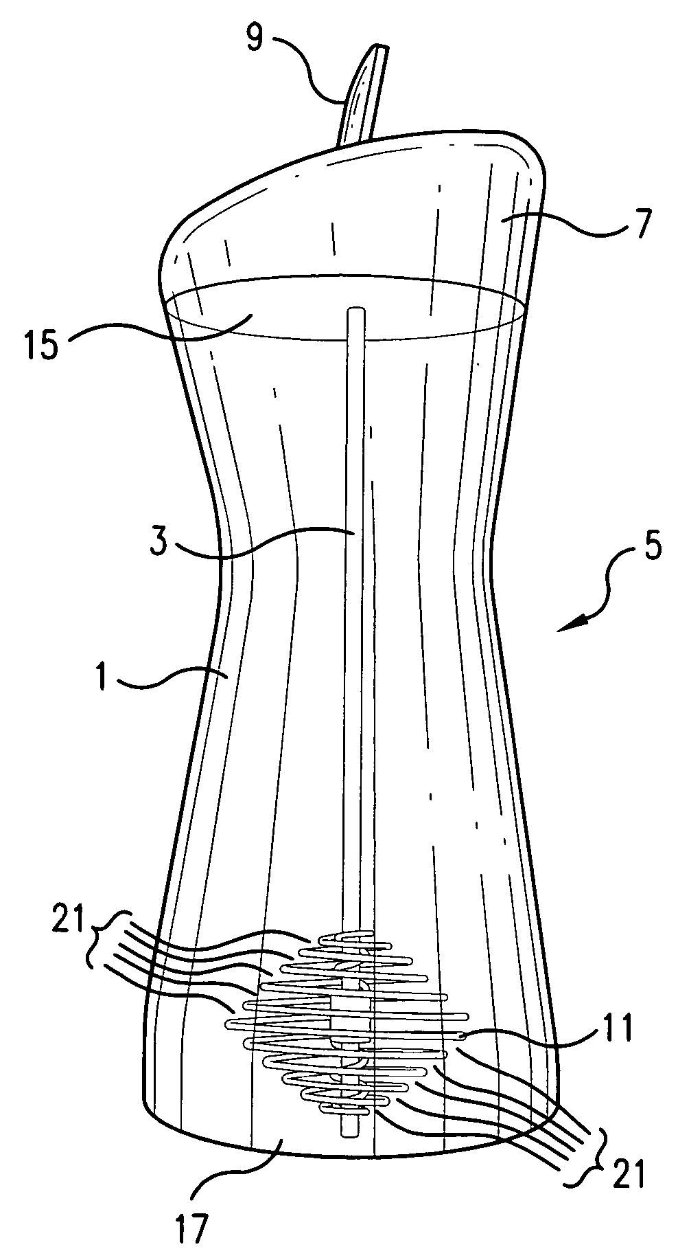
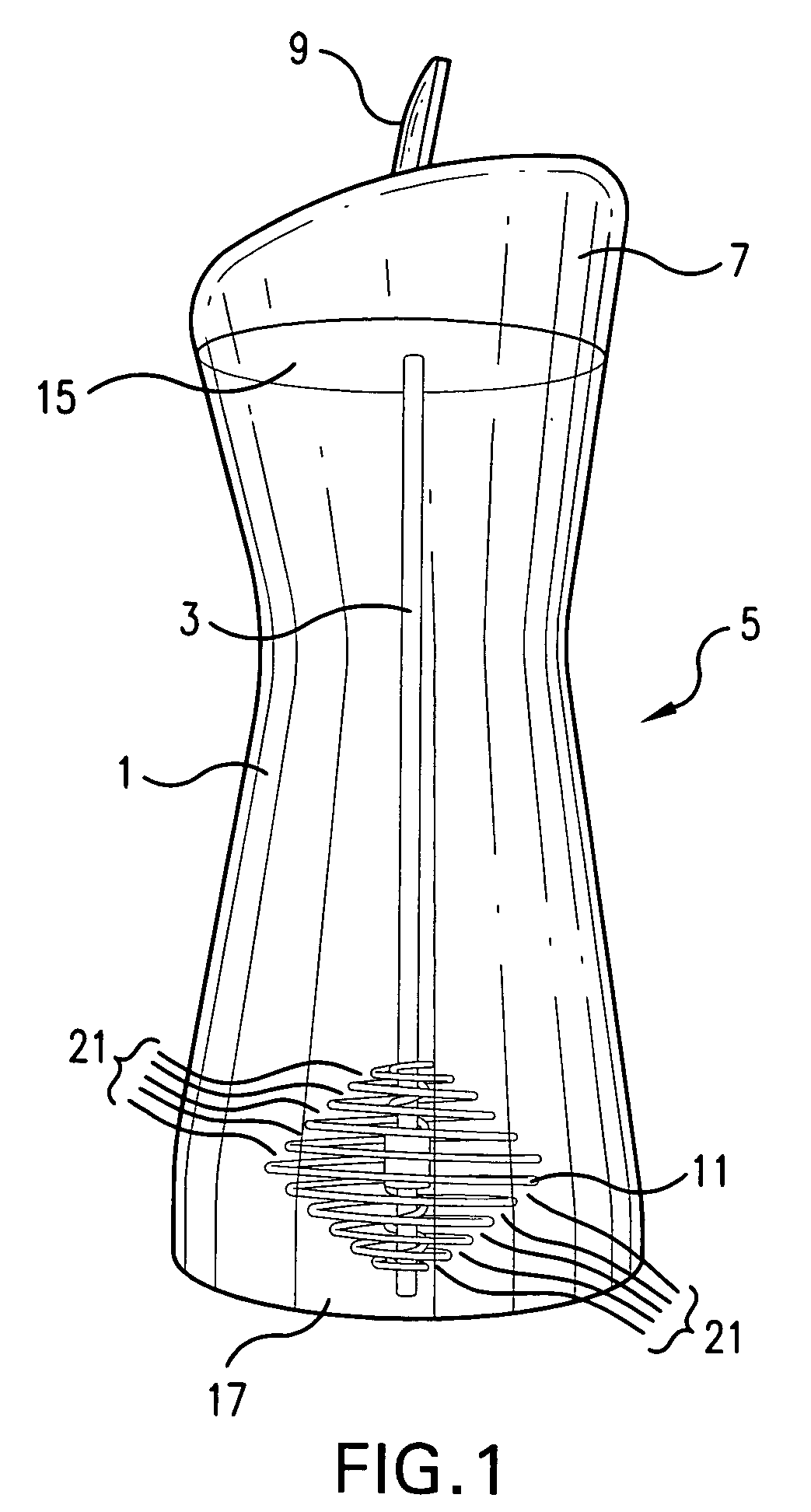
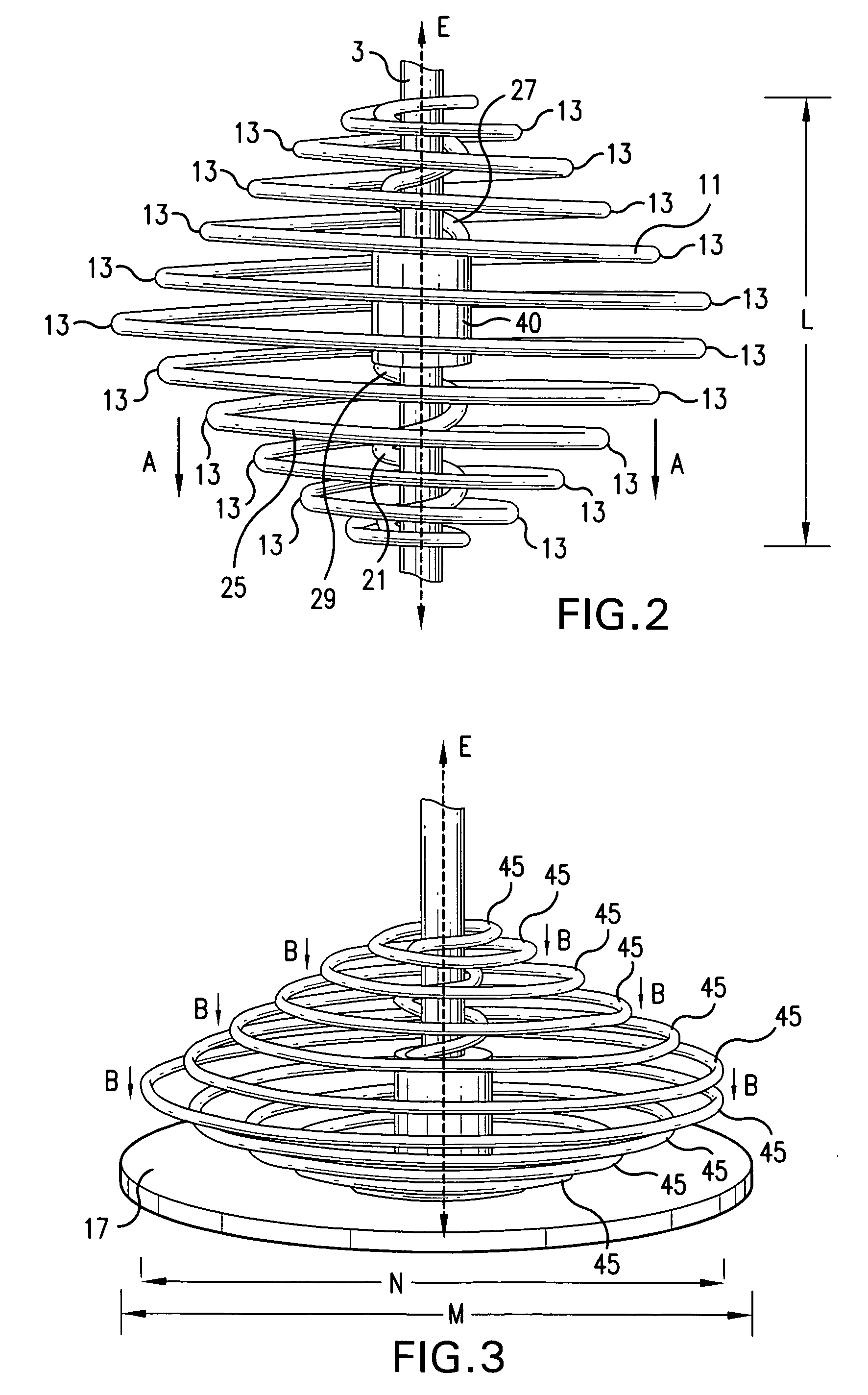
[0027] Referring to FIG. 1, shaker 5 includes mixing vessel 1, screw-on top 7, snap-lid 9, guide rod 3, and spring agitator 11. Solid and liquid mixture constituents are poured into vessel 1 through an opening in screw-on top 7. Snap-lid 9 is closed and the us...


PUM


Abstract

A handheld shaker with a reciprocating agitator, comprising a mixing vessel that operatively contains a guide rod that runs from one end of the vessel to an opposite end of the vessel. The mixing vessel is operatively connected to both such ends. The shaker also uses a hollow agitator frame that operatively reciprocates from the one end of the vessel to the opposite end, and thereby mixes fluid contained within the vessel. A reciprocating agitator is also disclosed.

Description

FIELD OF THE INVENTION [0001] The present invention relates to a shaker for mixing and agitating fluids. More particularly, the present invention relates to a shaker and agitator that mix liquids quickly, uniformly and easily. BACKGROUND OF THE INVENTION [0002] Pancake batters, dietary supplements drinks, baby formulas and nutritional shakes often require an agitation or dispersion mechanism for optimal mixing and dispersion of their powdered constituents. Several such mechanisms include an agitator attached to a mixing container. These attached or fixed agitators may have a semi-permanent connection to the container, or they may be manufactured integrally within the container. Several such devices are described in U.S. Pat. Nos. 1,060,419 and 3,136,532. These attached elements often create cracks and crevices, however, which are difficult to clean. Furthermore, these devices often do not allow sufficient movement or reach of the agitator to the entire container area, and thus fail ...

Claims


Application Information

Patent Timeline
Patent Type & Authority Applications(United States)
IPC IPC(8): A47J43/27
CPCA47J43/10B01F15/00512B01F11/0082A47J43/27B01F31/441B01F35/32021
Inventor VERNON, ROBERT D.
Owner RUNWAY BLUE LLC
Learn More