Image processing system and camera

a technology of image processing and camera, applied in the field of image processing system and camera, can solve the problems of insufficient color reproducibility and high color reproducibility of patented cameras, and the size of images is difficult to match

Inactive Publication Date: 2006-11-09
OLYMPUS CORP
View PDF87 Cites 122 Cited by
  • Summary
  • Abstract
  • Description
  • Claims
  • Application Information

AI Technical Summary

Problems solved by technology

Further, these devices are also required to be small and lightweight and handy for the sake of examination operability.
H7-322103 are handy but the patent does not make these cameras adequate in terms of color reproducibility and high color reproducibility.
Further, the high color reproduction system to which the rotating filter type disclosed in Japanese Patent Application Laid Open No. 2000-152269 is applied is a fixed disposition type and heavy, and further because of the external illumination, it has required a special illumination sensor for the color reproduction processing.
Furthermore, in a conventional dental treatment, when the tooth color is selected, a comparative judgment is performed by means of a shade guide that shows the shade of the color as mentioned earlier but this comparative judgment is subjective and also affected by the deterioration and variation of indoor light, which has produced errors.
Further, although recording is performed by means of photography, confirmation of the camera settings is required, the sizes of the images are also hard to match, and accuracy is lacking in that the film sensitivity and film development sensitivity and so forth are not constant.
In addition, problems with color reproduction image systems to which a conventional miniature photography device is applied include:
(2) there is the possibility of high brightness parts caused by the light source arising in the captured image data when the object is a regular reflection glossy object, and although this fact is resolved by means of a simple device, there have been no proposals in this regard either.
However, because the color chart is prepared separately from the photography device, storage management is required.
Because the archive management is performed by hand, the color chart is readily soiled and, depending on the management method, there is the possibility of degradation through exposure to external light.
However, no such proposal has been made.

Method used


Image

  • Image processing system and camera
  • Image processing system and camera
  • Image processing system and camera

Examples


second embodiment

[0351] FIGS. 17 to 20 and FIG. 100 show a second embodiment of the present invention. FIG. 17 is a block diagram showing the constitution of the image processing system, FIG. 18A and FIG. 18B are timing charts that show reading aspects in full mode and reading two-speed mode in the second embodiment, FIG. 19A and FIG. 19B show aspects of lines read in 2 / 4 line two-speed mode and 2 / 8 line four-speed mode, and FIG. 20 is a flowchart showing the operation when the photography mode is set.

[0352] In this second embodiment, the same numerals are assigned to the parts that are the same as those of the first embodiment above and a description thereof will be omitted only the differences are mainly described.

[0353] The second embodiment has the basic constitution of the first embodiment described earlier and is constituted to permit the adjustment of the image reading speed from a color CCD that comprises a color filter array (CFA) 19 at the front face thereof.

[0354] The image reading spe...

third embodiment

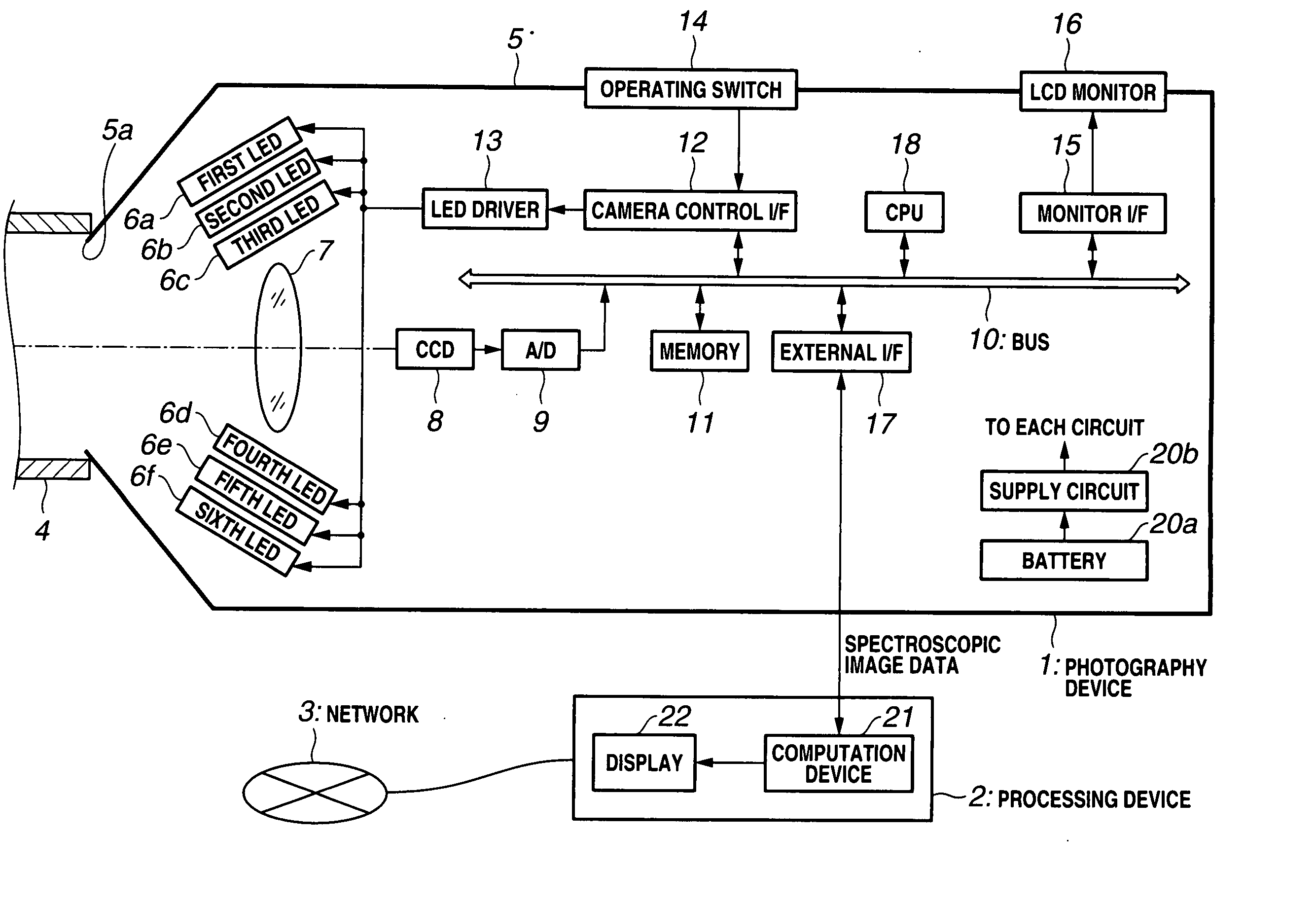
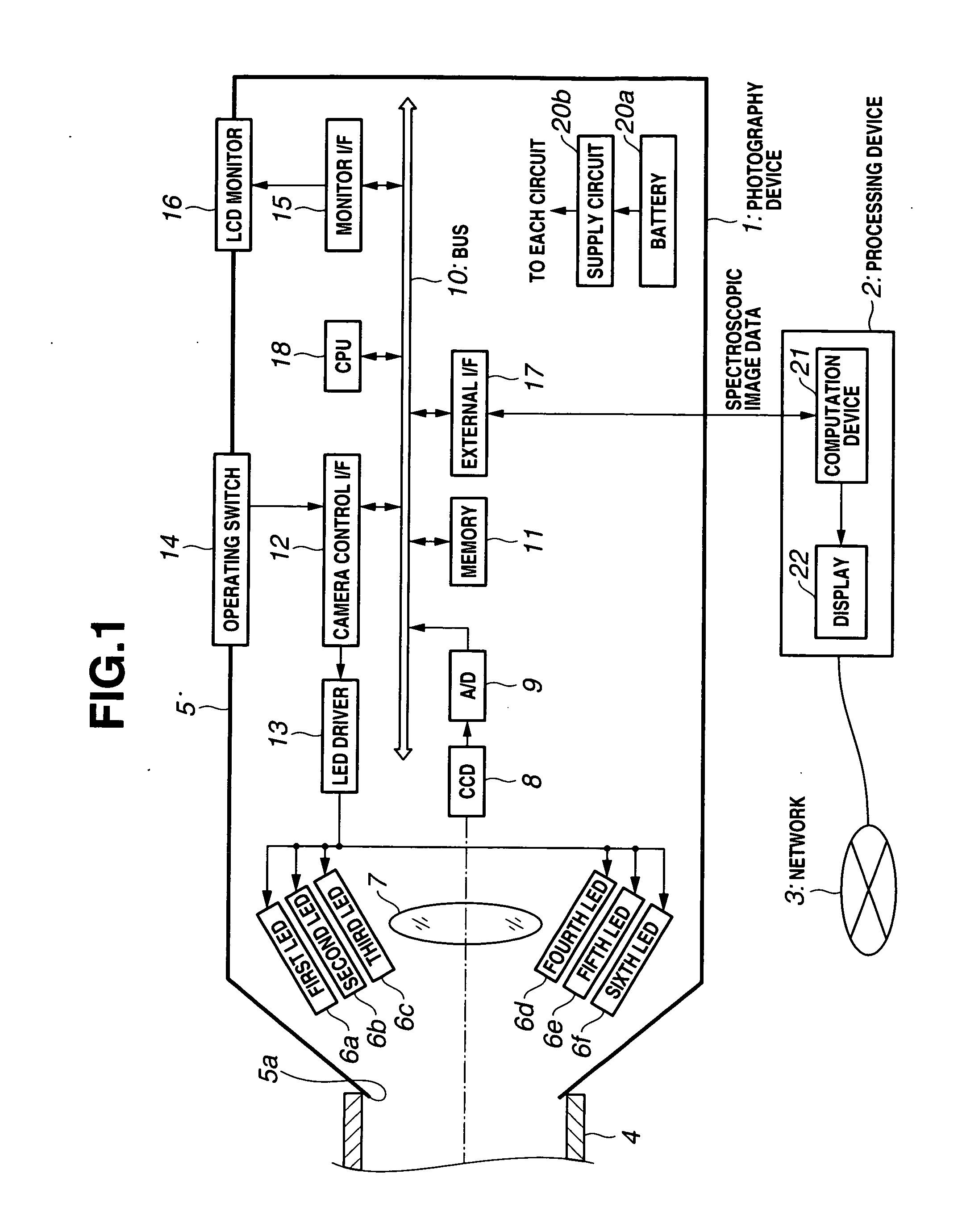
[0389] FIGS. 21 to 36 show a third embodiment of the present invention. FIG. 21 is a block diagram showing the constitution of an image processing system and FIG. 22 shows an example of an aspect when the image processing system is used. In the third embodiment, the same numerals are assigned to the parts that are the same as those of the first and second embodiments above and a description of these parts will be omitted. Only the differences are mainly described.

[0390] The third embodiment has the basic constitution of the first embodiment described earlier and is constituted such that a three-band color filter array is installed on the photographic face of the CCD.

[0391] That is, as shown in FIGS. 21 and 22, the photography device 1 has an RBG 3-band color filter array (abbreviated as CFA in FIG. 21) 19 installed in the vicinity of the CCD 8 in the light path in which the object image is formed by the photography optical system 7 and a so-called single-panel-type color image pic...

fourth embodiment

[0456] FIGS. 37 to 42 and FIG. 89 show a fourth embodiment of the present invention. FIG. 37 is a block diagram showing the constitution of the image processing system. In the fourth embodiment, the same numerals are assigned to the same parts as those of the first to third embodiments and a description of such parts is omitted. Only the differences are mainly described.

[0457] The fourth embodiment has the basic constitution of the third embodiment above and is further constituted by adding a spectral detection sensor.

[0458] That is, as shown in FIG. 37, the photography device 1 of the image processing system is constituted further comprising: in addition to the constitution of the third embodiment shown in FIG. 21, a spectral detection sensor 41 that detects the spectral distribution of light; a probe 42 that introduces detected light to the spectral detection sensor 41; a sensor I / F 43 that converts the output from the spectral detection sensor 41 into a digital signal and proce...


PUM


Abstract

The image processing system is applied to dentistry, for example, and performs photography of the teeth of a patient while causing a plurality of illumination light LEDs of different wavelengths to emit light by means of a photography device when producing a crown repair or denture of the patient, whereby image data are acquired. The image data are transmitted to a dental filing system constituting a processing device where color reproduction data are determined through computation. In addition, color reproduction data are transmitted to the dental technician's office via a public switched network. Therefore, a repair material compound ratio calculation database is searched and the compound data for a material that matches the hue of the patient's teeth are found, whereby a crown repair or denture or the like that very closely matches the color of the patient's teeth is produced.

Description

CROSS REFERENCE TO RELATED APPLICATION [0001] This application is a continuation application of PCT / JP2005 / 000783 filed on Jan. 21, 2005 and claims benefit of Japanese Application No. 2004-016264 filed in Japan on Jan. 23, 2004, the entire contents of which are incorporated herein by this reference. BACKGROUND OF THE INVENTION [0002] 1. Field of the Invention [0003] The present invention relates to an image processing system and camera that acquire a spectroscopic spectral image information on an object, and perform highly accurate color reproduction, examination, and judgment and so forth on an image of the object from the acquired image information. [0004] 2. Description of the Related Art [0005] In recent years, there has been a growing interest in health and an increased need for whitening due to the pursuit of beauty. Conventionally, diagnoses using skin diagnosis cameras have been provided in dermatology, esthetic salons, and beauty counseling and so forth. In the case of derm...

Claims


Application Information

Patent Timeline
Patent Type & Authority Applications(United States)
IPC IPC(8): G03B41/00A61B5/00G01J3/02G01J3/10G01J3/50G03B15/00
CPCA61B5/4547G01J3/02G01J3/0218G01J3/0224G01J3/0264G01J3/0272A61B5/0013G01J3/10G01J3/50G01J3/501G01J3/508G01J3/51G01J3/0291
Inventor KONNO, OSAMUKOMIYA, YASUHIROWADA, TORUSATO, NOBUMASA
Owner OLYMPUS CORP
Why Eureka
Try Eureka