Orthodontic devices for use with arch wires

a technology of orthodontic devices and arch wires, applied in the field of orthodontic devices, can solve the problems of not being able to meet the needs of patients, not always convenient, and more difficult to implemen

Inactive Publication Date: 2006-11-09
AUGUSTA DEV INC
View PDF8 Cites 23 Cited by
  • Summary
  • Abstract
  • Description
  • Claims
  • Application Information

AI Technical Summary

Benefits of technology

[0012] It is another principal object to provide new devices of small size and of an exterior shape that makes them specially suitable for use in lingual techniques, particularly in association with incisor or canine teeth.
[0023] In the slot closed position a portion of the integral extension may be positively engaged with a surface of the device body so as to preload the integral portion and thereby urge the free end portion toward engagement with an arch wire in the arch wire slot, and also in this position the integral extension may be engaged by lateral walls of the device body parallel to an occlusal, gingival, labial, lingual plane to protect it against mesial or distal directed stresses applied thereto.

Problems solved by technology

This is not always convenient, and may not be possible when the tube is on an intermediate tooth, and the solution is then to use a tube of the so-called convertible type, with which one side of the tube bore can be opened when required for insertion of the wire therein, or its removal.
There is increasing interest in the lingual technique, even though such procedures are more difficult to implement.
The compromise is not so suitable for older patients who tend to show their lower teeth more, and in some cases primarily display their lower anterior teeth.
Attempts simply to reduce the size of existing devices are not generally successful, at least partly because changes in scale affects size parameters in different ratios, e.g. areas decrease in square ratio while volumes decrease in cube ratio, with the result that it becomes increasingly difficult, especially with the tiny spring members required, to find materials of the necessary properties.

Method used


Image

  • Orthodontic devices for use with arch wires
  • Orthodontic devices for use with arch wires
  • Orthodontic devices for use with arch wires

Examples


Embodiment Construction

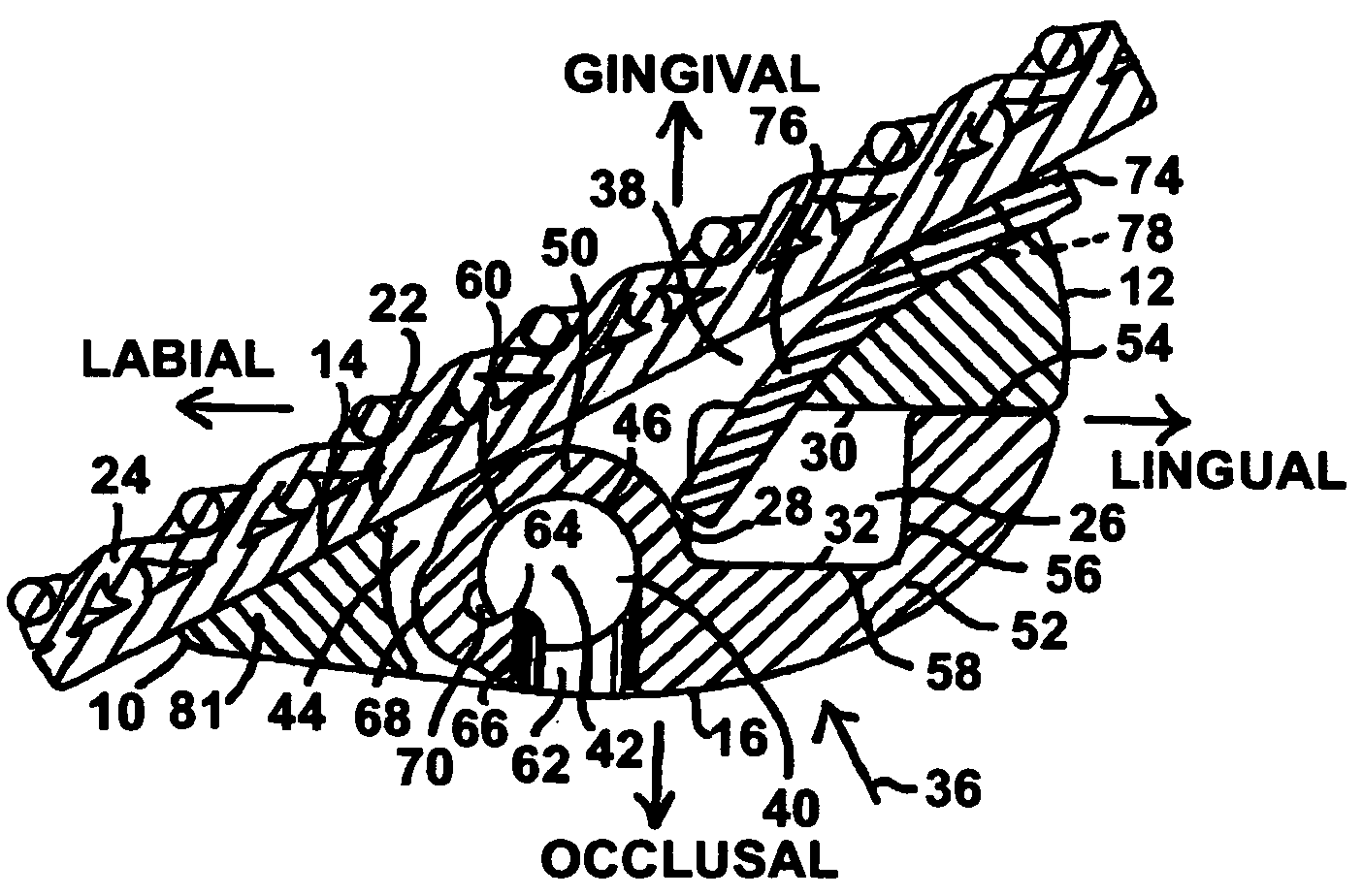
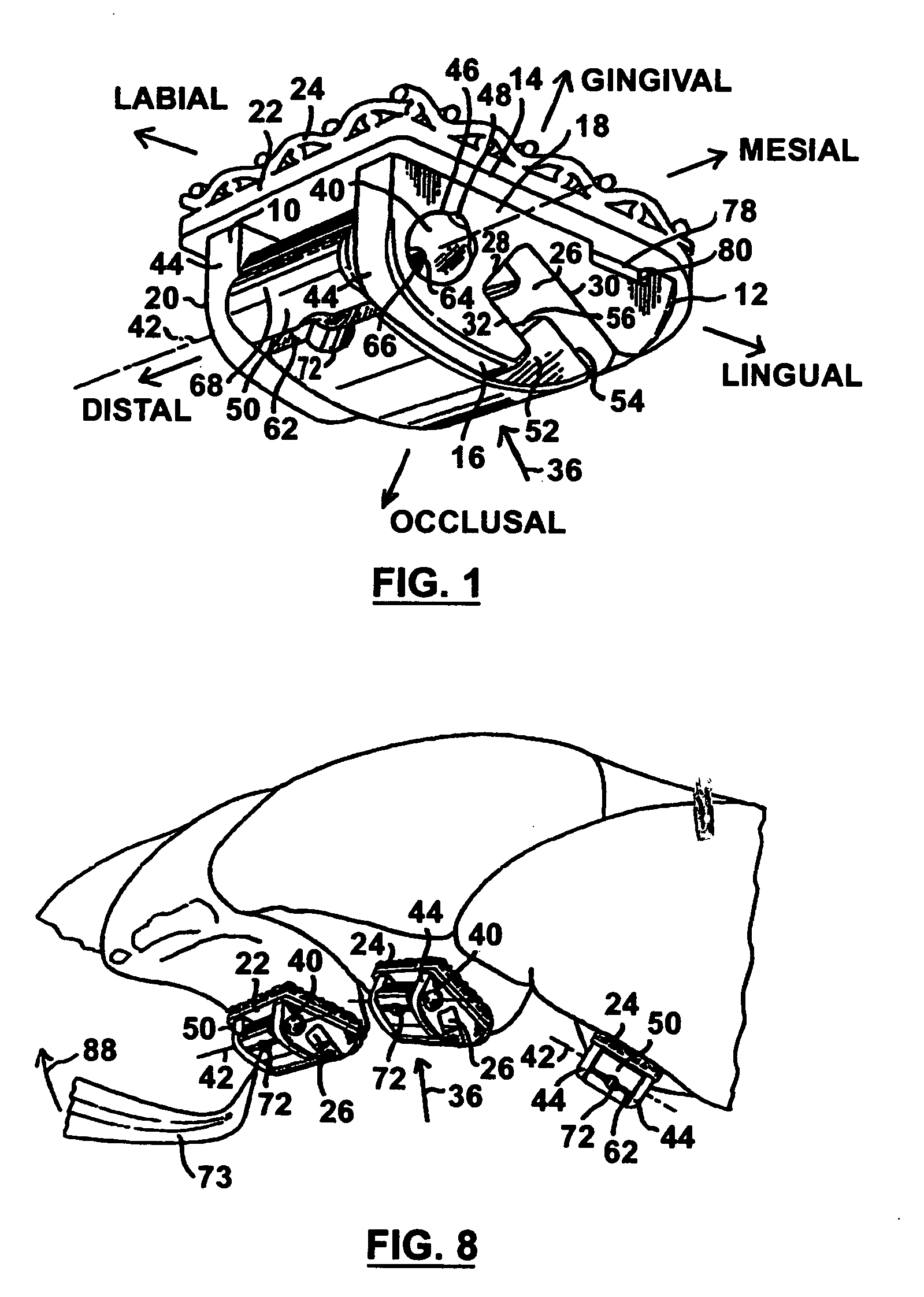
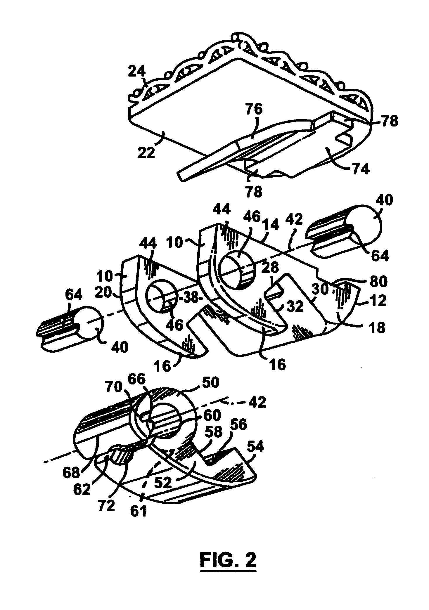
[0041] Similar parts are given the same reference number in all the Figures of the drawings wherever this is appropriate. It may be noted that the devices shown in FIGS. 1 through 11 are intended to be used attached to the lingual surfaces of incisor or canine teeth, while those shown in FIGS. 12-14 are intended to be used attached to the lingual surfaces of bicuspid or molar teeth.

[0042] In this specification and the appended claims, for convenience in language the devices and parts thereof are referred to, unless otherwise specified, as they would be used mounted in the upper arch region of a patient's mouth, especially since the brackets described are intended primarily for use in lingual procedures. However, all of the brackets of the invention may be used for either labial or lingual procedures. The labial and lingual direction designations are reversed between the two procedures, e.g. the bracket surface referred to as the labial surface in the labial procedure becomes the li...


PUM


Abstract

An orthodontic bracket or convertible buccal tube for use with arch wires has the usual mesial distal extending slot having one side open to receive the wire. The open side is closed by a shutter pivoting on a pivot pin, or coaxial pins, about a mesial distal axis, the shutter being latched in slot closed position to retain the arch wire in the slot. The device includes an attitude controlling spring member consisting of an integral extension of the part of the shutter member that closes the slot, the extension being thinner and therefore of greater flexibility than the relatively rigid shutter member. The extension can be progressively thinner that the shutter member from its junction therewith to a free end that engages the arch wire in the slot. In slot closed position a portion of the integral extension is positively engaged with a surface of the device body so as to preload the spring. Also in slot closed position the integral extension is engaged by lateral walls of the device body parallel to an occlusal, gingival, labial, lingual plane to protect it against mesial or distal directed stresses applied thereto.

Description

CROSS REFERENCE TO A RELATED APPLICATION [0001] This application is a continuation of my prior application Ser. No. 10 / 623,528, filed 22 Jul., 2003, the priority of which is claimed under 35USC120.FIELD OF THE INVENTION [0002] This invention is concerned with improvements in or relating to orthodontic devices consisting of orthodontic brackets and convertible type tubes that are used in orthodontic procedures in cooperation with arch wires, and particularly such devices which have arch wire attitude controlling spring means as a permanent part thereof. BACKGROUND OF THE INVENTION [0003] Orthodontic procedures almost always employ a plurality of orthodontic brackets that are attached to respective teeth, usually by cementing them thereto, although in some circumstances the bracket may still be attached to a metal band which embraces the tooth. Each bracket has a mesial distal extending slot therein, usually of rectangular cross section in a gingival occlusal plane, and the brackets a...

Claims


Application Information

Patent Timeline
Patent Type & Authority Applications(United States)
IPC IPC(8): A61C3/00A61C7/28A61C7/30
CPCA61C7/145A61C7/30A61C7/285A61C7/28A61C7/00
Inventor HANSON, G. HERBERT
Owner AUGUSTA DEV INC
Why Eureka
Try Eureka