
Dosing dispenser particularly useful for dispensing baby formula

Inactive Publication Date: 2006-11-16
AMIR TAL
View PDF22 Cites 23 Cited by
  • Summary
  • Abstract
  • Description
  • Claims
  • Application Information

AI Technical Summary

Benefits of technology

[0005] According to one aspect of the present invention, there is provided a dosing dispenser of the character described, wherein the dispenser further comprises a restraining device effective, when the dosing device has been moved away from the first limit position towards the second limit position, to restrain a return movement of the dosing device back to the first limit position until the dosing device has first completed its movement to the second limit position, to thereby prevent dispensing less than the predetermined quantity of the flowable material by only a partial filling of the dosing compartment.
[0006] According to another aspect of the present invention, there is provided a dosing dispenser of the character described, wherein the dispenser further comprises a vibrator device effective to vibrate the housing by the movement of the dosing device between its limit positions so as to enhance the flow of the flowable material into and out of the dosing compartment.

Problems solved by technology

However, the known constructions generally suffer from one or more of the following drawbacks: Some constructions do not prevent the user from accidentally dispensing less than the desired predetermined quantity of flowable material.
Others do not assure complete filling and / or complete emptying of their respective dosing compartments.
Still others do not provide the user with the possibility of dispensing more than one predetermined quantity of flowable material.
Many others are of a construction difficult to produce and / or to keep clean.
Such drawbacks generally make the known dosage dispenser constructions relatively unsuitable for use to dispense baby formula.

Method used


Image

  • Dosing dispenser particularly useful for dispensing baby formula
  • Dosing dispenser particularly useful for dispensing baby formula
  • Dosing dispenser particularly useful for dispensing baby formula

Examples


Embodiment Construction

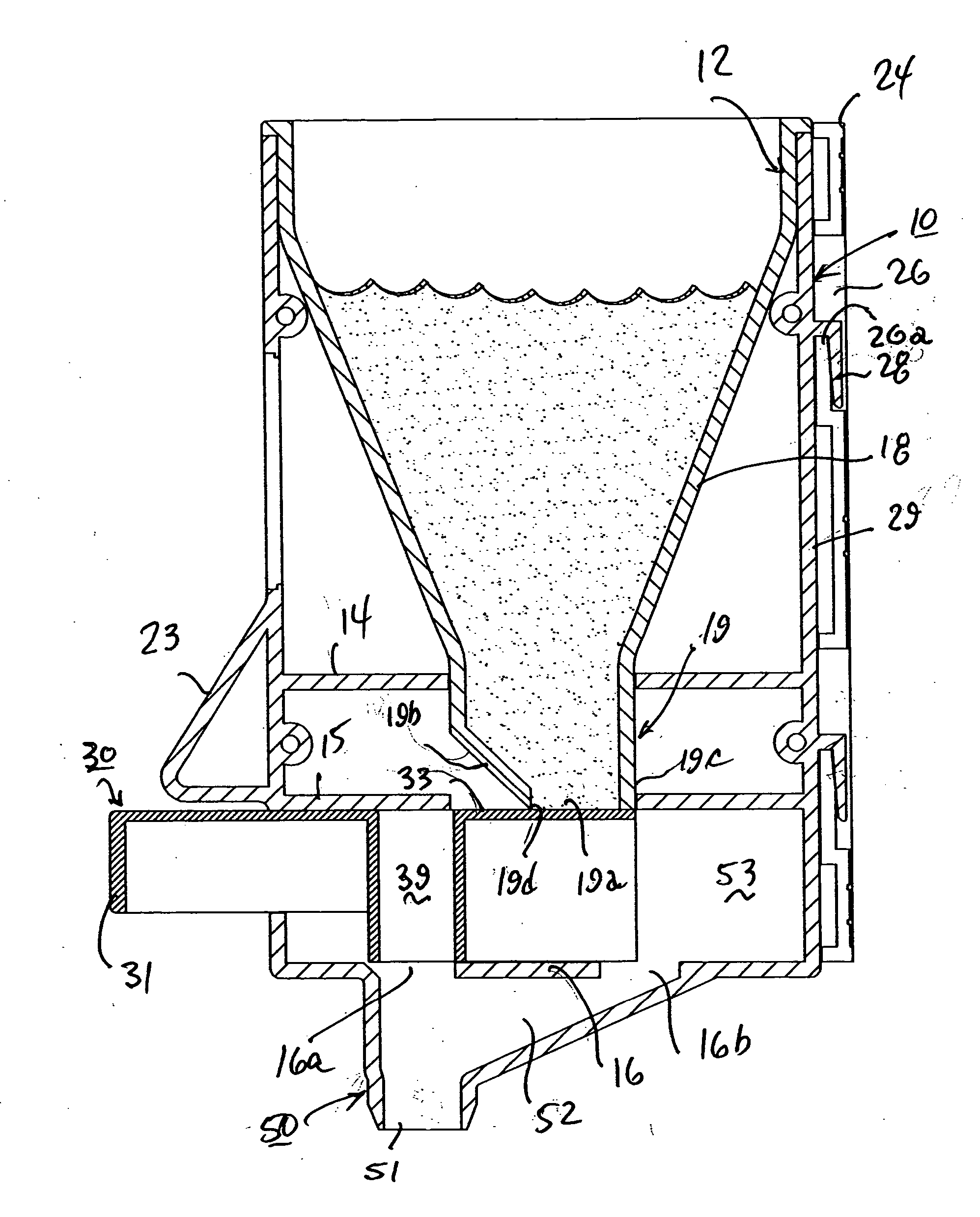
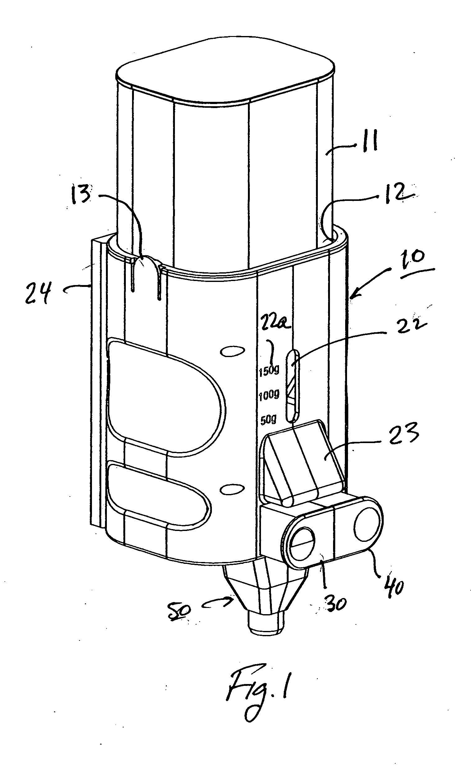
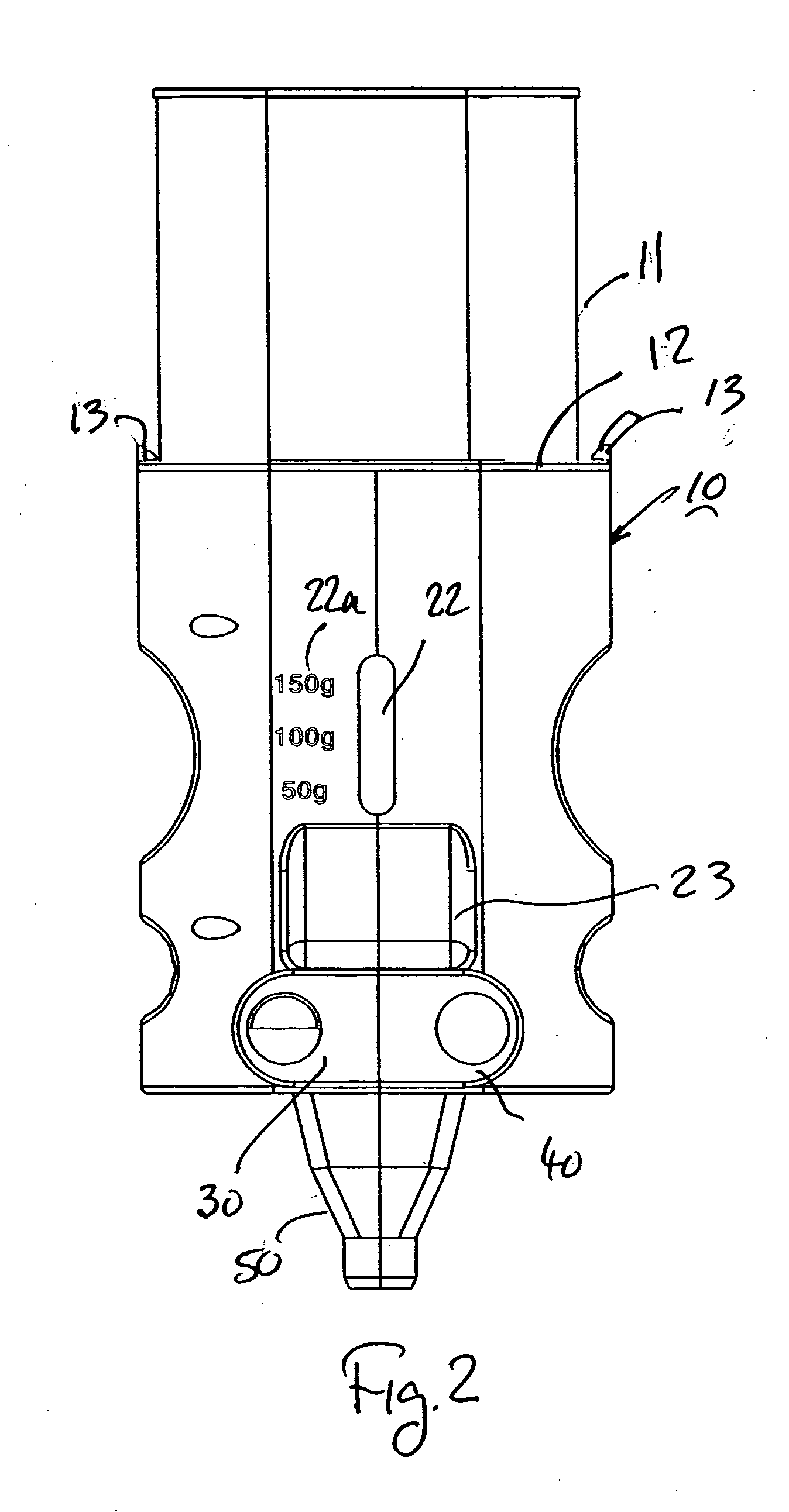
[0018] The dosing device illustrated in the drawings is particularly useful for dispensing predetermined quantities of baby formula into a baby bottle, but could be used for dispensing other flowable materials, e.g. powdered soap, sugar, coffee, etc.

[0019] The illustrated disposing dispenser includes a housing, generally designated 10, for receiving a receptacle 11 containing a bulk quantity of the flowable material, e.g. baby formula in powder form. In this case, receptacle 11 may be the original package in which the baby formula is sold to the consumer. Preferably, it is held in a holder 12 which is releasably retained within housing 10 by a pair of spring clips 13 at the opposite sides of the housing engageable with the upper edge of the holder.

[0020] The interior of housing 110 includes two vertically-spaced horizontal walls, 14, 15 (e.g. FIG. 3), each formed with a cut-out 14a, 15a, for receiving the lower end of holder 12. The interior of housing 10 includes a further horizo...


PUM


Abstract

A dosing dispenser for dispensing predetermined quantities of a flowable material, particularly baby formula, includes a dosing device having a dosing compartment located to align its upper end with a receptacle for the flowable material, when the dosing device is in a rear limit position, for filling with the flowable material, and to align its lower end with a dispensing outlet when the dispensing device is in a forward limit position for dispensing the flowable material in the dosing compartment from the housing. The dispenser further includes a restraining device for restraining movement of the dosing device, when starting a movement in one direction, against movement in the opposite direction until the dosing device has completed its movement in the one direction, to thereby prevent dispensing of less than the predetermined quantity of the flowable material by only a partial filling of the dosing compartment. A vibratory action is produced when the dosing device is proved in either direction to enhance the flow of the flowable material into and out of the dosing compartment.

Description

FIELD AND BACKGROUND OF THE INVENTION [0001] The present invention relates to dosing dispensers for dispensing predetermined quantities of a flowable material. The invention is particularly useful for dispensing predetermined quantities of a baby formula into a baby bottle, and is therefore described below with respect to such an application, but it will be appreciated that the invention could advantageously be used in many other applications as well. [0002] Many constructions of dosing dispensers are known for dispensing predetermined quantities of flowable materials, as described for example in U.S. Pat. Nos. 1,471,621, 2,046,068, 3,193,159, 4,186,646 and 5,462,101. However, the known constructions generally suffer from one or more of the following drawbacks: Some constructions do not prevent the user from accidentally dispensing less than the desired predetermined quantity of flowable material. Others do not assure complete filling and / or complete emptying of their respective dos...

Claims


Application Information

Patent Timeline
IPC IPC(8): G01F11/10B67D7/56
CPCG01F11/18
Inventor AMIR, TAL
Owner AMIR TAL
Learn More