Fuel injector with electromagnetic actuator

a technology of electromagnetic actuator and fuel injector, which is applied in the direction of fuel injection apparatus, spraying apparatus, feeding system, etc., can solve the problems of high precision and compromise combustion, and achieve the effect of simple and economical production

Inactive Publication Date: 2006-11-16
FAB ITAL MAGNETI MARELLI SPA
View PDF17 Cites 27 Cited by
  • Summary
  • Abstract
  • Description
  • Claims
  • Application Information

AI Technical Summary

Benefits of technology

[0008] The object of the present invention is to provide a fuel injector with an electromagnetic actuator which does not exhibit the above-stated disadvantages and, in particular, is simple and economic to produce.

Problems solved by technology

However, such injectors do not ensure a high level of precision and of stability in directing fuel injection and such injectors are accordingly unsuitable for use in “spray-guided” engines, in which the fuel must be injected with a very high level of precision in the vicinity of the spark plug; indeed, in this kind of application, an error of less than one millimetre in the direction of the stream of fuel may result in wetting of the spark plug electrodes, so seriously compromising combustion.

Method used


Image

  • Fuel injector with electromagnetic actuator
  • Fuel injector with electromagnetic actuator
  • Fuel injector with electromagnetic actuator

Examples


Embodiment Construction

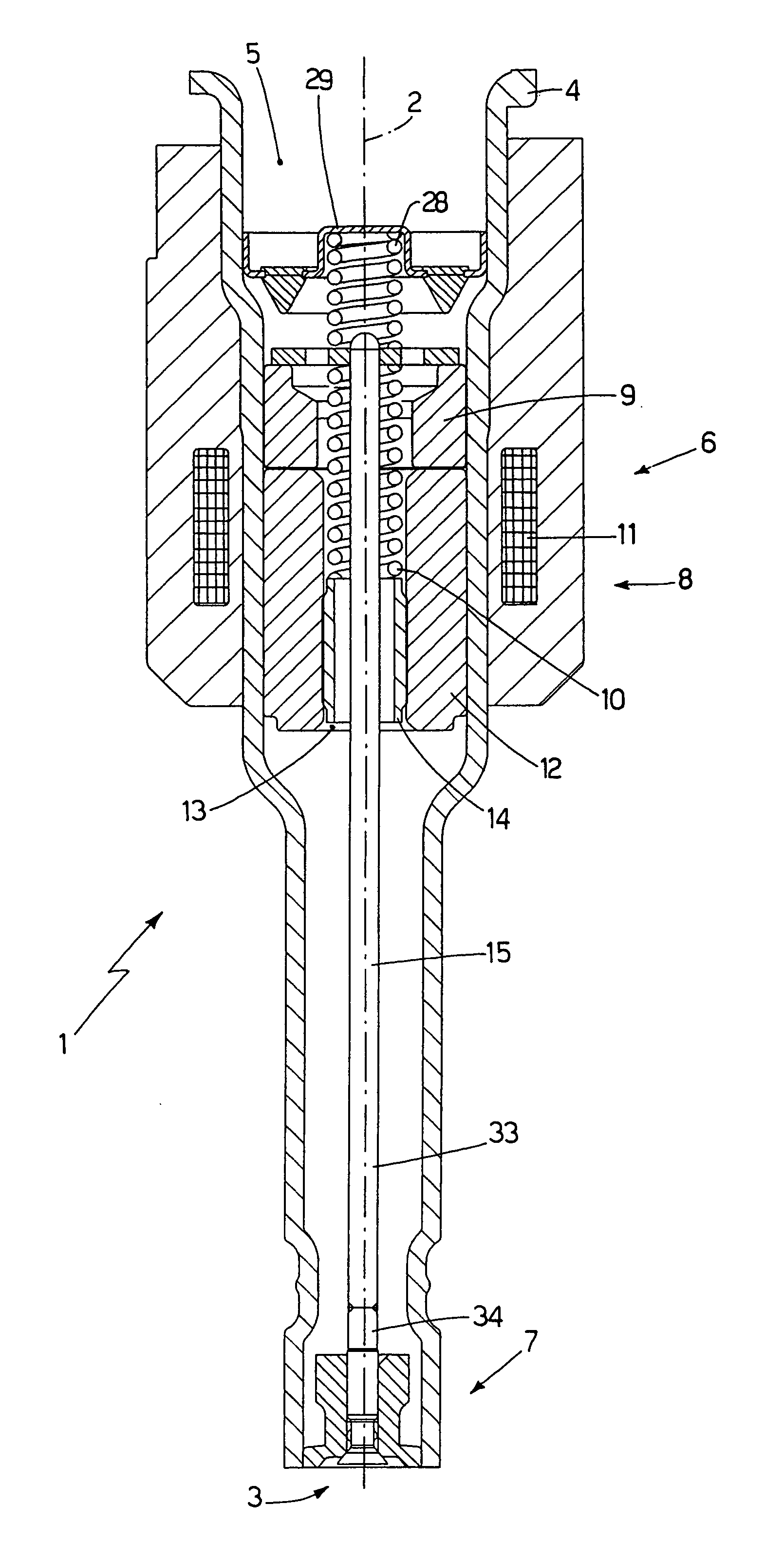
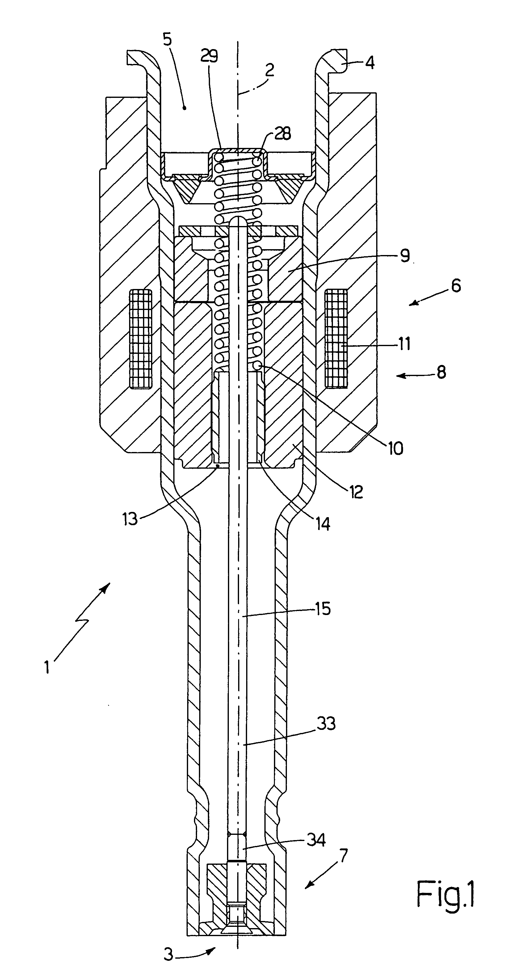
[0014] In FIG. 1, 1 denotes the overall fuel injector which exhibits a substantially cylindrical symmetry around a longitudinal axis 2 and is capable of being operated to inject fuel from an injection jet 3 which opens directly into an explosion chamber (not shown) of a cylinder. The injector 1 comprises a monolithic support body 4, which is of a cylindrical tubular shape of variable cross-section along the longitudinal axis 2 and comprises a feed channel 5 extending over the entire length of said support body 4 in order to supply the fuel under pressure towards the injection jet 3. The support body 4 accommodates an electromagnetic actuator 6 at the level of an upper portion of said support body and an injection valve 7 at the level of a lower portion of said support body; in operation, the injection valve 7 is actuated by the electromagnetic actuator 6 in order to control the flow of fuel through the injection jet 3, which is located at the level of said injection valve 7.

[0015] ...


PUM


Abstract

A fuel injector equipped with an injection valve comprising a mobile plunger ending with a sealing head; a support body having a tubular shape and comprising a feed channel; and a sealing body, in which is defined a valve seat of the injection valve; the sealing head is of a frustoconical shape, is arranged externally relative to the guide element, is thrust by a spring against said guide element in a direction contrary to the direction of feed of the fuel; the valve seat has a frustoconical shape which is a negative reproduction of the frustoconical shape of the sealing head in order to impart an internally hollow conical shape to the injected fuel.

Description

[0001] The present invention relates to a fuel injector with an electromagnetic actuator. [0002] The following explanations will make explicit reference, without consequently restricting the general scope thereof, to an injector with an electromagnetic actuator for direct fuel injection. BACKGROUND OF THE INVENTION [0003] An electromagnetic fuel injector comprises a cylindrical tubular body having a central feed channel which performs the function of a fuel duct and ends with an injection jet controlled by an injection valve operated by an electromagnetic actuator. The injection valve is provided with a plunger, which is rigidly connected to a mobile armature of the electromagnetic actuator in order to be displaced by the action of said electromagnetic actuator between a closed position and an open position of the injection jet against the action of a spring which tends to hold the plunger in the closed position. The plunger ends with a sealing head which, in the closed position, is...

Claims


Application Information

Patent Timeline
Patent Type & Authority Applications(United States)
IPC IPC(8): F02M61/08
CPCF02M51/0671F02M61/08F02M61/18F02M61/162F02M61/168F02M61/12
Inventor CRISTIANI, MARCELLOPASQUALI, PAOLO
Owner FAB ITAL MAGNETI MARELLI SPA
Why Eureka
Try Eureka