
Color pixels with anti-blooming isolation and method of formation

a color pixel and isolation technology, applied in the field of high quantum efficiency cmos image sensor, can solve problems such as undesirable blooming, and achieve the effect of reducing cross-talk and reducing blooming

Inactive Publication Date: 2006-11-16
APTINA IMAGING CORP
View PDF11 Cites 31 Cited by
  • Summary
  • Abstract
  • Description
  • Claims
  • Application Information

AI Technical Summary

Benefits of technology

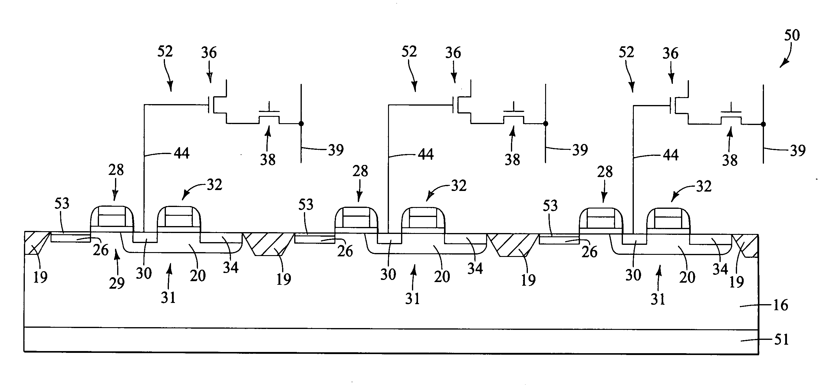
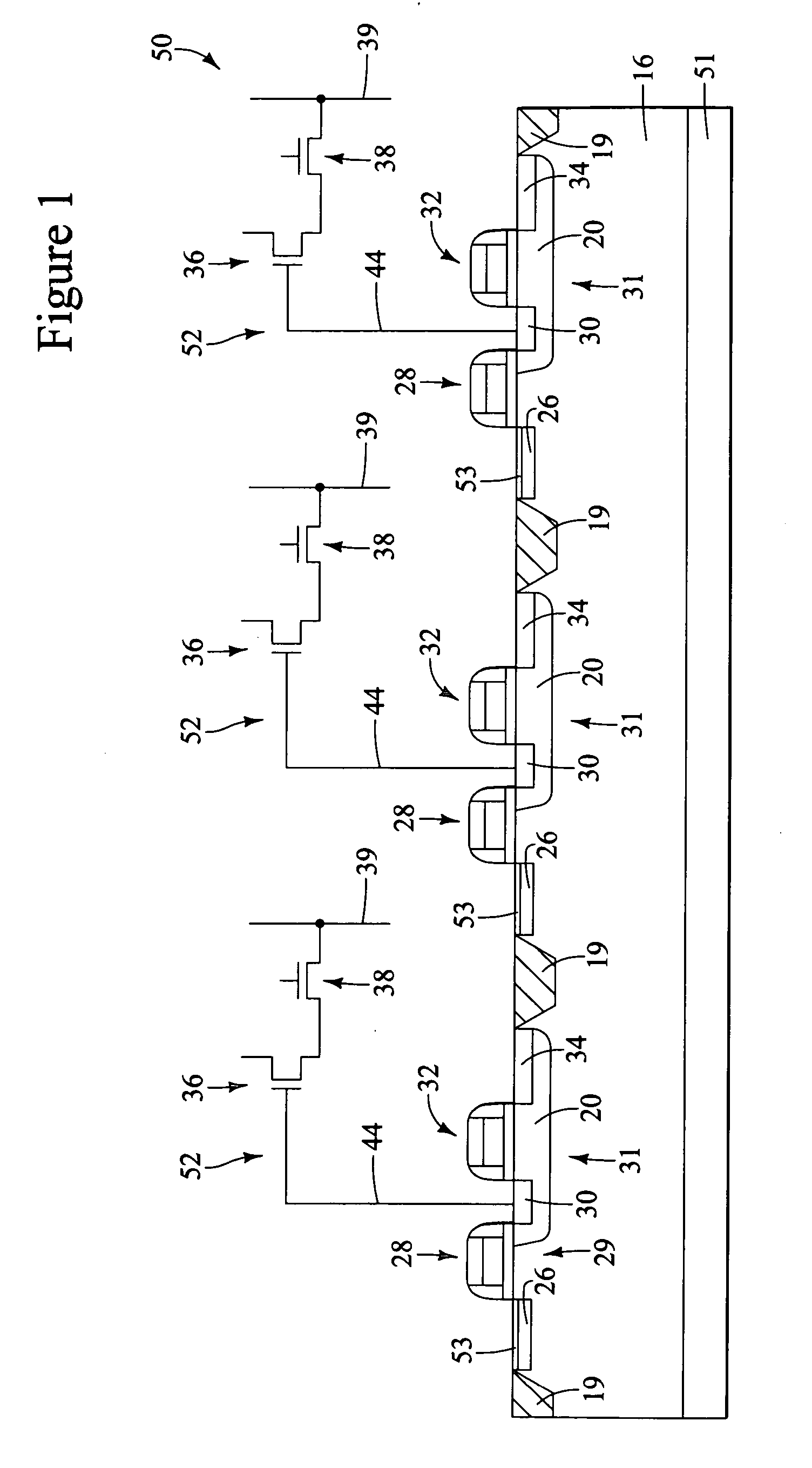
[0013] To further reduce cross-talk between adjacent pixels and to decrease blooming, an anti-blooming region of a sec

Problems solved by technology

Another problem often associated with photodiodes is that of blooming.
Blooming is undes

Method used


Image

  • Color pixels with anti-blooming isolation and method of formation
  • Color pixels with anti-blooming isolation and method of formation
  • Color pixels with anti-blooming isolation and method of formation

Examples


Embodiment Construction

[0026] In the following detailed description, reference is made to the accompanying drawings which form a part hereof, and in which is shown by way of illustration specific embodiments in which the invention may be practiced. These embodiments are described in sufficient detail to enable those skilled in the art to practice the invention, and it is to be understood that other embodiments may be utilized, and that structural, logical and electrical changes may be made without departing from the spirit and scope of the present invention.

[0027] The terms “wafer” and “substrate” are to be understood as a semiconductor-based material including silicon, silicon-on-insulator (SOI) or silicon-on-sapphire (SOS) technology, doped and undoped semiconductors, epitaxial layers of silicon supported by a base semiconductor foundation, and other semiconductor structures. Furthermore, when reference is made to a “wafer” or “substrate” in the following description, previous process steps may have be...


PUM


Abstract

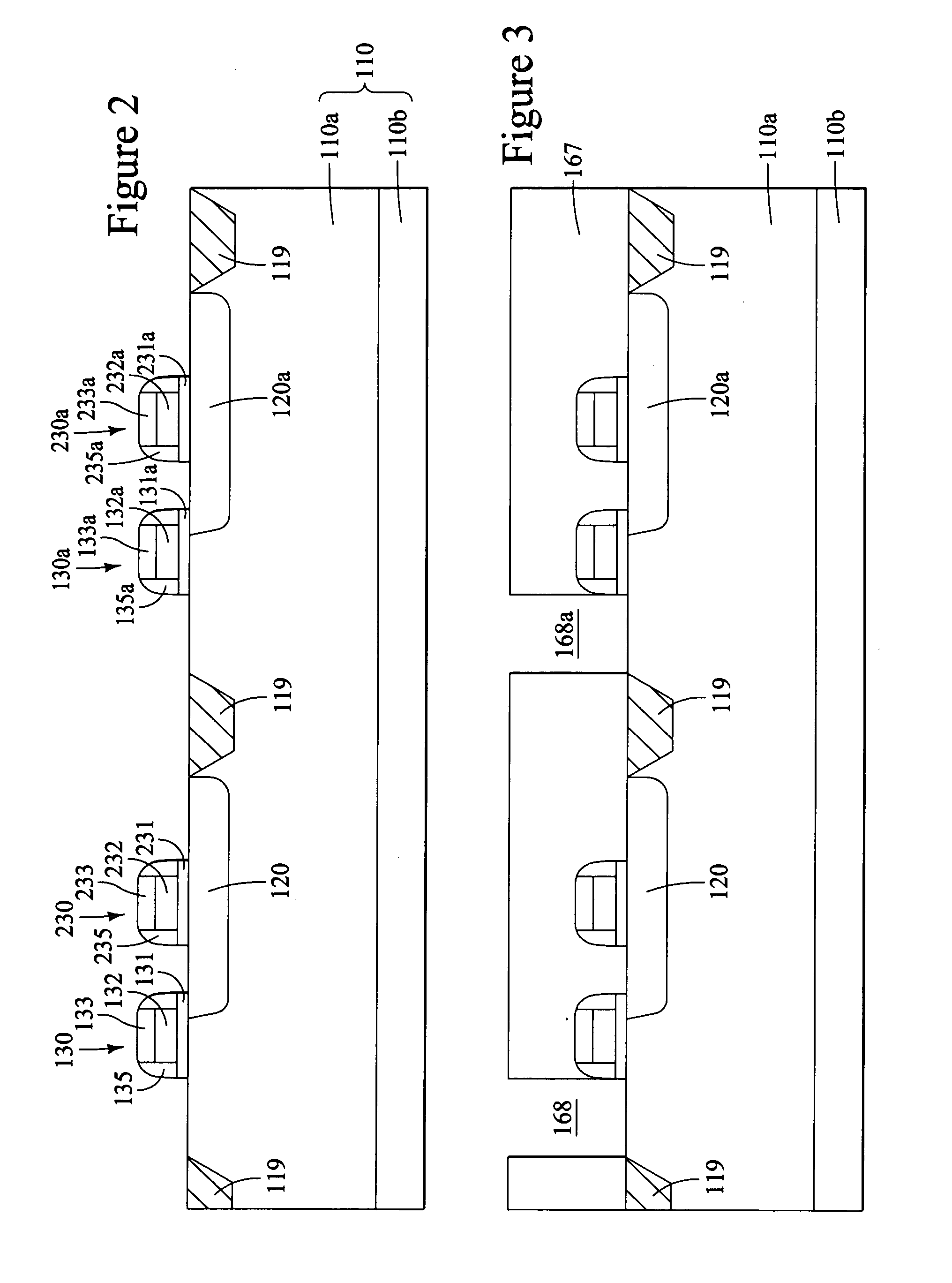
Implant regions of a first conductivity type are formed under at least a portion of a first pixel sensor cell and of a second pixel cell to limit the depth of the photodiode collection/depletion region and limit the pixel's color response. To further reduce cross-talk between adjacent pixels and to decrease blooming, an anti-blooming isolation region of a second conductivity type is formed in the substrate and below the stop implant regions of the first conductivity type.

Description

FIELD OF THE INVENTION [0001] The present invention relates to the field of semiconductor devices and, in particular, to high quantum efficiency CMOS image sensors having an anti-blooming structure. BACKGROUND OF THE INVENTION [0002] Imagers typically consist of an array of pixel cells containing photosensors, where each pixel produces a signal corresponding to the intensity of light impinging on that element when an image is focused on the array. These signals may then be stored, for example, to display a corresponding image on a monitor or otherwise used to provide information about the optical image. The photosensors are typically phototransistors, photoconductors, photogates or photodiodes. The magnitude of the signal produced by each pixel, therefore, is proportional to the amount of light impinging on the photosensor. [0003] To allow the photosensors to capture a color image, the photosensors must be able to separately detect red (R) photons, green (G) photons and blue (B) pho...

Claims


Application Information

Patent Timeline
IPC IPC(8): H01L27/148
CPCH01L27/14609H01L27/1463H01L27/14689H01L27/14687H01L27/14656H01L27/146
Inventor PATRICK, INNALADD, JOHN
Owner APTINA IMAGING CORP
Learn More