Ultrasonic probe

a technology of ultrasonic probes and probes, applied in ultrasonic/sonic/infrasonic diagnostics, mechanical vibration separation, instruments, etc., can solve the problems of manufacturing difficulty, small phase controllable range, and difficult to obtain ultrasonic images with high resolution, and achieve high resolution and resolution. high

Inactive Publication Date: 2006-11-16
PANASONIC CORP
View PDF8 Cites 13 Cited by
  • Summary
  • Abstract
  • Description
  • Claims
  • Application Information

AI Technical Summary

Benefits of technology

[0007] The present invention has been developed with a view to solving the above-mentioned problems, and it is an object of the invention to provide an ultrasonic probe capable of realizing a desired ultrasonic wave directivity at each of positions in a direction perpendicular to an arraying direction of piezoelectric elements, thus lowering the ultrasonic wave directivity, carrying out phase-control through the use of an array of a large number of piezoelectric elements without restraint, narrowing an ultrasonic beam down, deflecting an ultrasonic beam, and obtaining an ultrasonic image with a high resolution.
[0030] According to the present invention, since the ultrasonic wave directivity can be set at a desired characteristic in accordance with a position in a direction perpendicular to the piezoelectric element arraying direction, the phase control is executable freely through the use of the array of many piezoelectric elements, and the ultrasonic waves can be narrowed down and deflected, thereby providing an ultrasonic probe which can produce an ultrasonic image with a high resolution.

Problems solved by technology

However, the structure of the above-mentioned conventional ultrasonic probe creates the following problems.
There is a problem which arises with the conventional structure, however, in that, since the central portion forming a position in each of the piezoelectric elements 91 in the X-direction shows a high directivity, the phase-controllable range becomes small, which makes it difficult to obtain an ultrasonic image with a high resolution.
However, this structure causes each of the piezoelectric elements 91 to have a larger thickness at both the end portions so that its column becomes high, whereupon an extreme difficulty arises in manufacturing.

Method used


Image

  • Ultrasonic probe
  • Ultrasonic probe
  • Ultrasonic probe

Examples


first embodiment

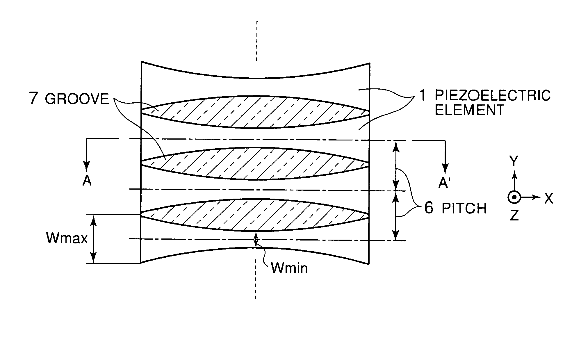
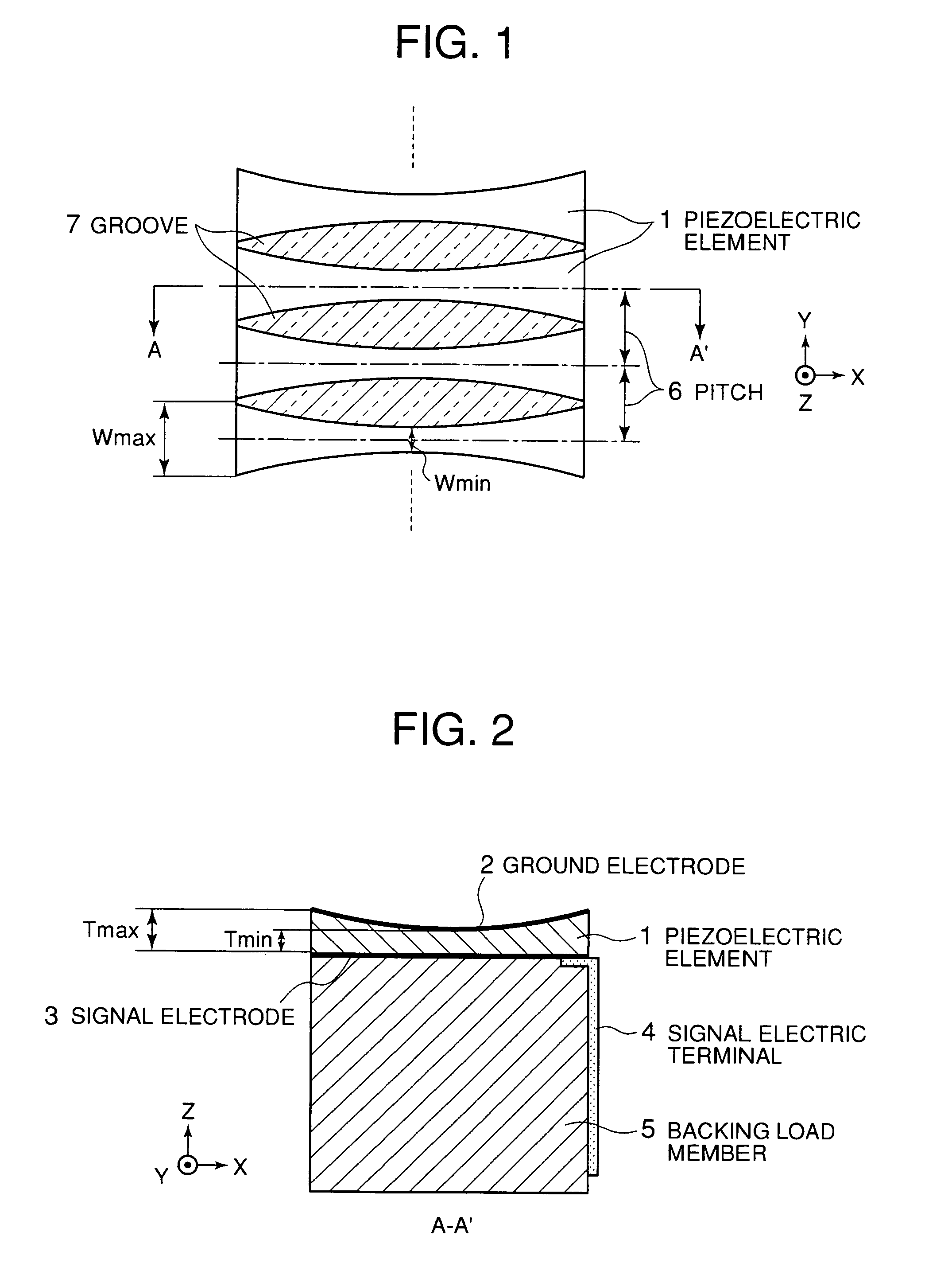
[0052] Ultrasonic probes according to embodiments of the present invention will be described hereinbelow with reference to the drawings. An ultrasonic probe according to a first embodiment of the present invention is shown in FIGS. 1 and 2. FIG. 1 is a top view and FIG. 2 is a side cross-sectional view taken along a line A-A′ in FIG. 1.

[0053] In FIGS. 1 and 2, this ultrasonic probe is made up of a plurality of piezoelectric elements 1 arrayed or arranged in a Y-direction for transmission / reception of ultrasonic waves in a Z-direction, a common ground electrode 2 provided on top surfaces of the piezoelectric elements 1, a plurality of signal electrodes 3 each provided on a base of each of the piezoelectric elements 1, a plurality of signal electric terminals 4 each for fetching a signal from each of the signal electrodes 3, and a backing load member 5 having a function to mechanically hold the backs of the piezoelectric elements 1 and further to attenuate an unnecessary ultrasonic s...

second embodiment

[0064] Furthermore, FIGS. 3 and 4 are illustrations of an ultrasonic probe according to a second embodiment of the present invention. In FIGS. 3 and 4, this ultrasonic probe is made up of a plurality of piezoelectric elements 11 arrayed in the Y-direction for transmission / reception of ultrasonic waves in the Z-direction, a common ground electrode 12 located on top surfaces of the piezoelectric elements 11, a plurality of signal electrodes 13 each provided on a back of each of the piezoelectric elements 11, a plurality of signal electric terminals 14 each for fetching a signal from each of the signal electrodes 13, and a backing load member 5 having a function to mechanically hold the backs of the piezoelectric elements 11 and further to attenuate an unnecessary ultrasonic signal when needed. The piezoelectric elements 11 are made of a piezoelectric ceramic such as PZT-based material, monocrystal or the like. The ground electrode 12 and the signal electrodes 13 are formed on the top ...

third embodiment

[0073] FIGS. 5 to 8 are illustrations of an ultrasonic probe according to a third embodiment of the present invention. This ultrasonic probe is made up of a plurality of piezoelectric elements 21 arrayed in the Y-direction for transmission / reception of ultrasonic waves in the Z-direction, a common ground electrode 22 located on top surfaces of the piezoelectric elements 21, acoustic matching layers 28 each formed as a one-or-more-layer structure (in this case, acoustic matching layers each formed as one layer), a plurality of signal electrodes 23 each provided on a back of each of the piezoelectric elements 21, a plurality of signal electric terminals 24 each for fetching a signal from each of the signal electrodes 23, and a backing load member 25 having a function to mechanically hold the backs of the piezoelectric elements 21 and further to attenuate an unnecessary ultrasonic signal when needed. The piezoelectric elements 21 are made of a piezoelectric ceramic such as PZT-based ma...


PUM

PropertyMeasurementUnit
frequencyaaaaaaaaaa
sound velocityaaaaaaaaaa
thicknessaaaaaaaaaa

Abstract

Disclosed is a technique of setting an ultrasonic wave directivity at a desired characteristic in accordance with position in a direction perpendicular to an arraying direction of piezoelectric elements. According to this technique, in a structure in which piezoelectric elements 1 are arrayed in a Y direction and each of the piezoelectric elements 1 is divided in a direction X perpendicular to the arraying direction Y, the width W of each of the piezoelectric elements 1 in the arraying direction is set at a minimum value at a central portion forming a position in the direction X perpendicular to the arraying direction Y while it is made wider toward both end portions, thus setting an ultrasonic directivity at a desired characteristic according to position in the X direction.

Description

TECHNICAL FIELD [0001] The present invention relates to an ultrasonic probe for use in ultrasonic diagnostic equipment and other apparatus. BACKGROUND ART [0002] As FIG. 21 shows, in a conventional ultrasonic probe, a plurality of piezoelectric elements 91 are arrayed in a Y-direction for transmission and reception of ultrasonic waves and a backing load member 92 is provided on the backs of the piezoelectric elements 91 for the attenuation of unnecessary ultrasonic waves transmitted from the piezoelectric elements 91 and further for holding the piezoelectric elements 91 mechanically. In addition, the thickness of each of the piezoelectric elements 91 at a position in an X-direction perpendicular to the arraying direction Y is made thinner in the vicinity of the center thereof while being made thicker toward both the end portions thereof so that each of the piezoelectric elements 91 has a curved configuration uneven in thickness. The variation of thickness of each of the piezoelectri...

Claims


Application Information

Patent Timeline
Patent Type & Authority Applications(United States)
IPC IPC(8): H01L41/08G01N29/24A61B8/00B06B1/06H04R1/32H04R17/00
CPCB06B1/0629
Inventor SAITO, KOETSU
Owner PANASONIC CORP
Why Eureka
Try Eureka