Check patentability & draft patents in minutes with Patsnap Eureka AI!

Battery protecting circuit

Active Publication Date: 2006-11-16
TEXAS INSTR JAPAN
View PDF2 Cites 80 Cited by
  • Summary
  • Abstract
  • Description
  • Claims
  • Application Information

AI Technical Summary

Benefits of technology

[0043] A fourth aspect of the present invention, a type of battery protecting circuit is provided characterized by the following facts: the battery protecting circuit is for driving the first, second and third transistors of the battery device that has a secondary battery, a first and a second transistor connected in series between the power source terminal of the secondary battery and the external power source terminal and a third transistor connected between the connection middle point between said first transistor and said second transistor and the power source terminal of the secondary battery; the battery protecting circuit has a first driver that feeds the first driving signal to the control terminal of said first transistor, a second driver that feeds the second driving signal to the control terminal of said second transistor, a third driver that feeds the third driving signal to the control terminal of said third transistor, a mode selector that contains a mode selection terminal that applies a voltage corresponding to the voltage fed to the external power source terminal or a reference voltage, a fourth transistor that can be connected between the connection middle point between said first transistor and said second transistor and the control terminal of said second transistor, and a driver for feeding the fourth driving signal to the control terminal of said fourth transistor corresponding to the voltage applied on said mode selection terminal, a voltage monitoring

Problems solved by technology

As a result, with a small size and a light weight, the batteries can drive equipment for a long time.
On the other hand, for lithium batteries and other high-performance batteries, overcharging may lead to an abnormally high cell voltage, overdischarge may lead to too low a cell voltage, or, when an excessive charge / discharge current flows in the cell, degradation in characteristics and problems may readily take place in the structure.
Consequently, the charging current flowing to the battery becomes intermittent, and this is undesired.
Especially when NMOS transistor Q2 changes from OFF to ON, the current flowing to the battery may temporarily become higher than precharging current I2, and this may lead to degradation of the battery cells.

Method used


Image

  • Battery protecting circuit
  • Battery protecting circuit
  • Battery protecting circuit

Examples


Embodiment Construction

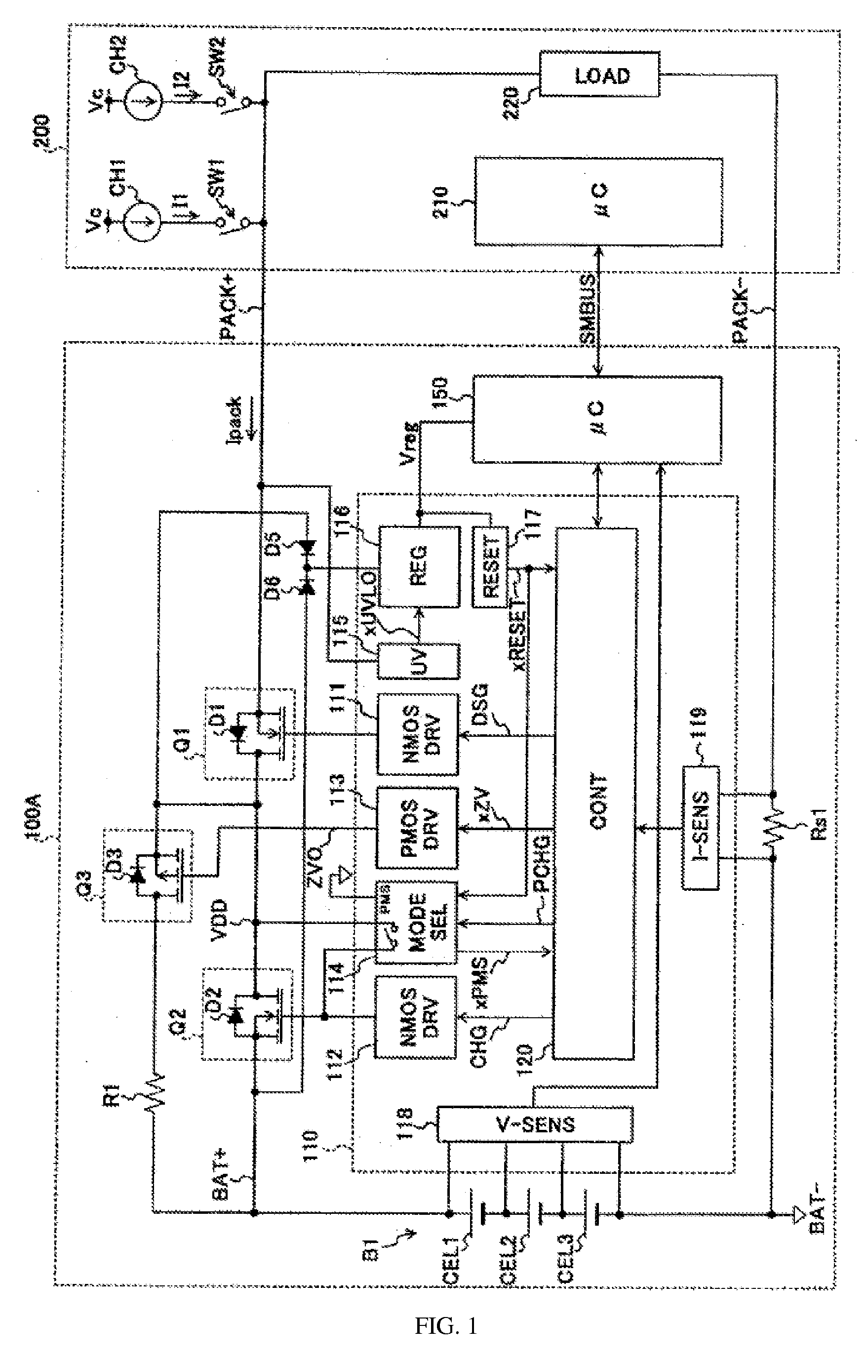
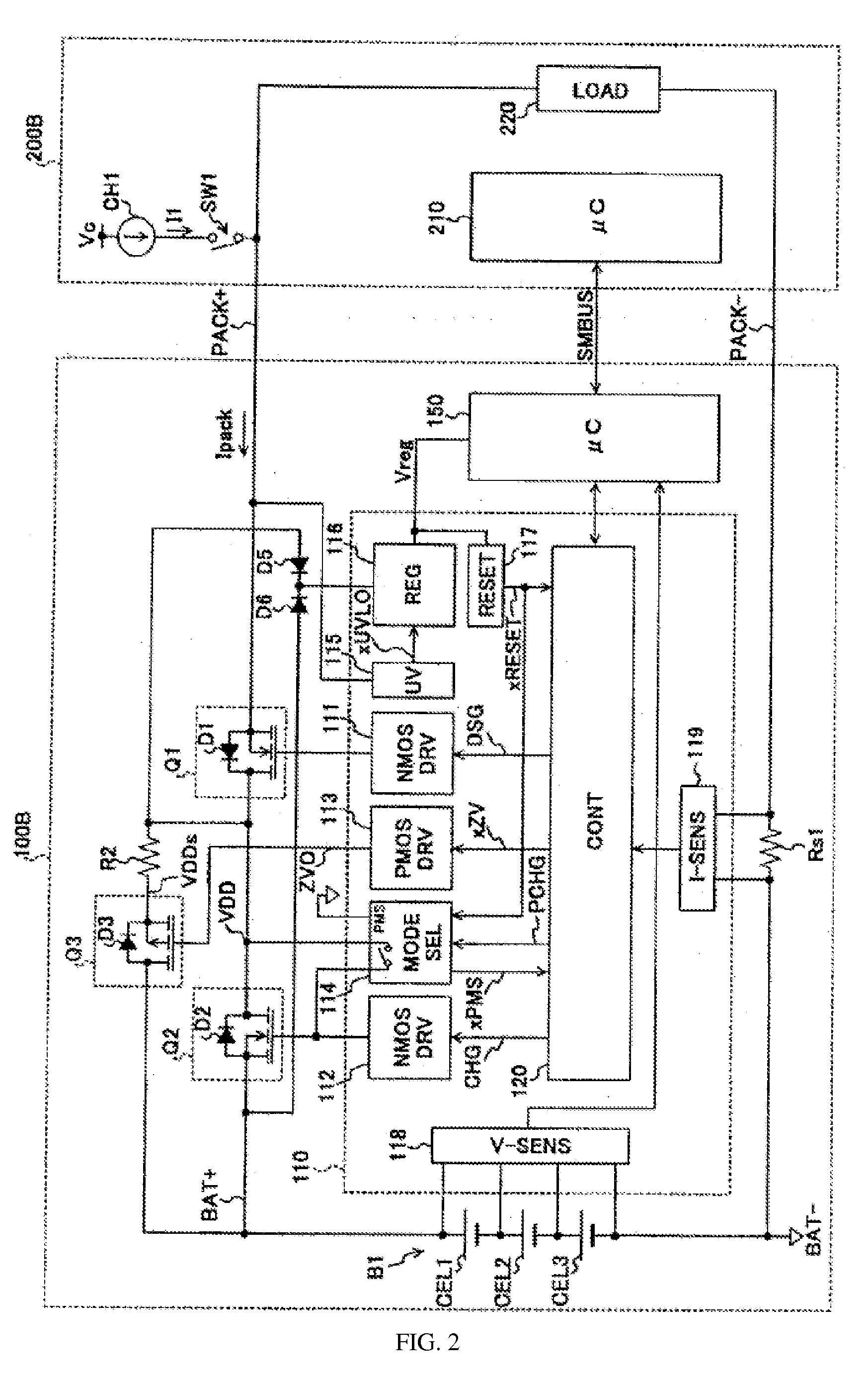
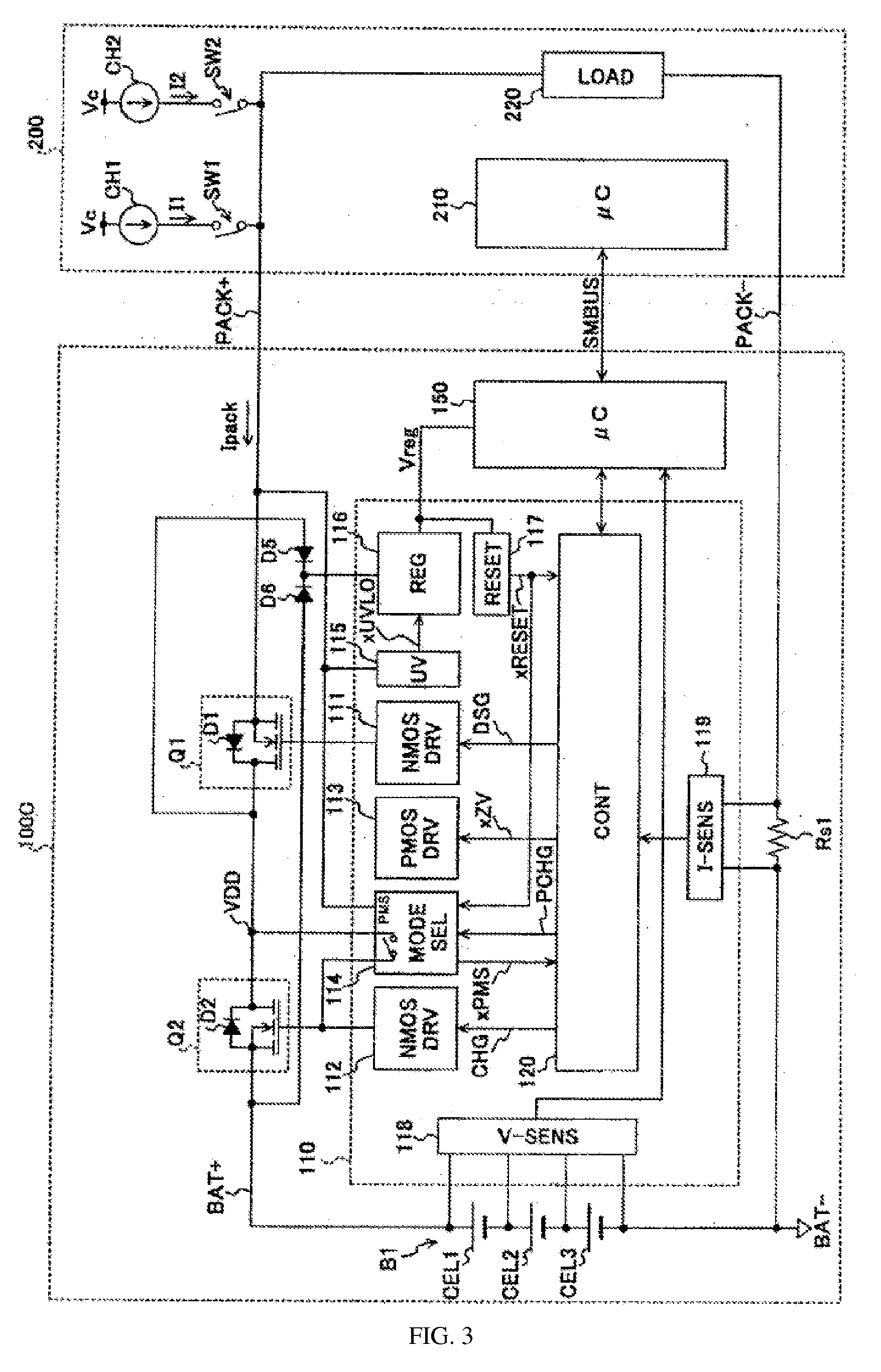
[0057] According to the present invention, when the battery voltage has not reached the voltage needed for the boosting operation for generating the driving voltage of the switching circuit, by turning ON a switching circuit that is inserted in another power feeding path and does not require the boosting operation, it is possible to charge the battery steadily with a constant charging current.

[0058] Also, according to the present invention, when the battery voltage has not reached the voltage needed for the boosting operation to generate the driving voltage of the switching circuit, by turning ON the switching circuit with a voltage sent from the external power source via the power feeding path, it is possible to charge the battery steadily with a constant charging current.

Optimum Embodiment of the Invention

[0059] In the following, an explanation will be given with reference to figures regarding the battery protecting circuit of the present invention adopted in a battery device....


PUM


Abstract

This invention provides a battery protecting circuit where even if the battery voltage falls nearly to zero volts due to overdischarge or the like while an NMOS transistor set in the power feeding path on the side of the positive electrode of the battery is turned ON / OFF, it is still possible to charge the battery by a constant charging current in a stable way. When the voltage of battery B1 has not reached the voltage needed for generating the driving voltage of NMOS transistors Q1, Q2 in drives 111, 112, the boosting operation of drives 111, 112 is stopped, and PMOS transistor Q3 inserted in a power feeding path different from that of said transistors is turned ON by driver 113. In driver 113, by clamping voltage VDD generated in the power feeding path of PMOS transistor Q3 to a voltage lower than it, driving voltage ZVO of PMOS transistor Q3 is generated without performing a boosting operation.

Description

FIELD OF THE INVENTION [0001] The present invention pertains to a type of battery protecting circuit that cuts off the power feeding path to protect the battery if an abnormality takes place in charging / discharging of the battery. For example, the present invention pertains to a type of battery protecting circuit that uses an n-channel MOS transistor as the switch for cutting off the power feeding path. BACKGROUND OF THE INVENTION [0002] In recent years, significant progress has been realized in increasing the energy density for lithium ion batteries, nickel-hydrogen batteries and other batteries having relatively small capacities. As a result, with a small size and a light weight, the batteries can drive equipment for a long time. Improvements in the performance of batteries have significantly contributed to the popularization of portable electronic equipment, as represented by cell phones. [0003] Also, with improvements in the performance of the battery itself, the performance of ...

Claims


Application Information

Patent Timeline
IPC IPC(8): H02J7/00
CPCH02J7/0029H02J2007/0039H02J7/0072H02J7/00304H02J7/007182
Inventor YOSHIO, KATSURA
Owner TEXAS INSTR JAPAN
Features
  • R&D
  • Intellectual Property
  • Life Sciences
  • Materials
  • Tech Scout
  • Unparalleled Data Quality
  • Higher Quality Content
  • 60% Fewer Hallucinations
Learn More