Ignition coil apparatus for an internal combustion engine

a technology of ignition coil and internal combustion engine, which is applied in the direction of coil manufacture, transformer/inductance details, inductance, etc., can solve the problems of inability to obtain a stable fusing state and increase the manufacturing cost accordingly, and achieve the effect of stable fusing sta

Active Publication Date: 2006-11-16
MITSUBISHI ELECTRIC CORP
View PDF5 Cites 12 Cited by
  • Summary
  • Abstract
  • Description
  • Claims
  • Application Information

AI Technical Summary

Benefits of technology

[0010] Accordingly, the present invention is intended to obviate the above-mentioned problems, and has for its object to obtain an ignition coil apparatus for an internal combustion engine which is capable of suppressing an increase in the manufacturing cost of a terminal of a low-tension side connector resulting from variation in a wire diameter at one end portion of a primary winding, and of ensuring a stable fusing state.
[0012] According to the ignition coil apparatus for an internal combustion engine of the present invention as constructed above, it is possible to suppress an increase in the manufacturing cost of the terminal of the low-tension side connector resulting from variation in the wire diameter of the one end of the primary winding, as well as to ensure a stable fusing state.

Problems solved by technology

In the ignition coil apparatus for an internal combustion engine as constructed above, the planar portion of the fusing portion and a main portion of the turned portion except the base end portion are parallel with respect to each other and are of planar shapes, thus posing the following problems.
(1) Since the radius of curvature R of the base end portion is set according to the cross-sectional shape of the one end of the primary winding, the terminal is required to have a radius of curvature of R matched to a wire diameter (i.e., the diameter of a winding wire or conductor) at the one end of the primary winding, and hence, a special press die is needed for that purpose and the manufacturing cost increases accordingly.
(2) Since the fusing portion is opened at a side opposite to the base end portion, there is a fear that the one end of the primary winding might be moved toward the side opposite to the base end portion when the secondary electrode is pushed to the primary electrode before fusing, so a current path formed at the time of fusing might vary in each fusing, thus making it impossible to obtain a stable fusing state.

Method used


Image

  • Ignition coil apparatus for an internal combustion engine
  • Ignition coil apparatus for an internal combustion engine
  • Ignition coil apparatus for an internal combustion engine

Examples


embodiment 1

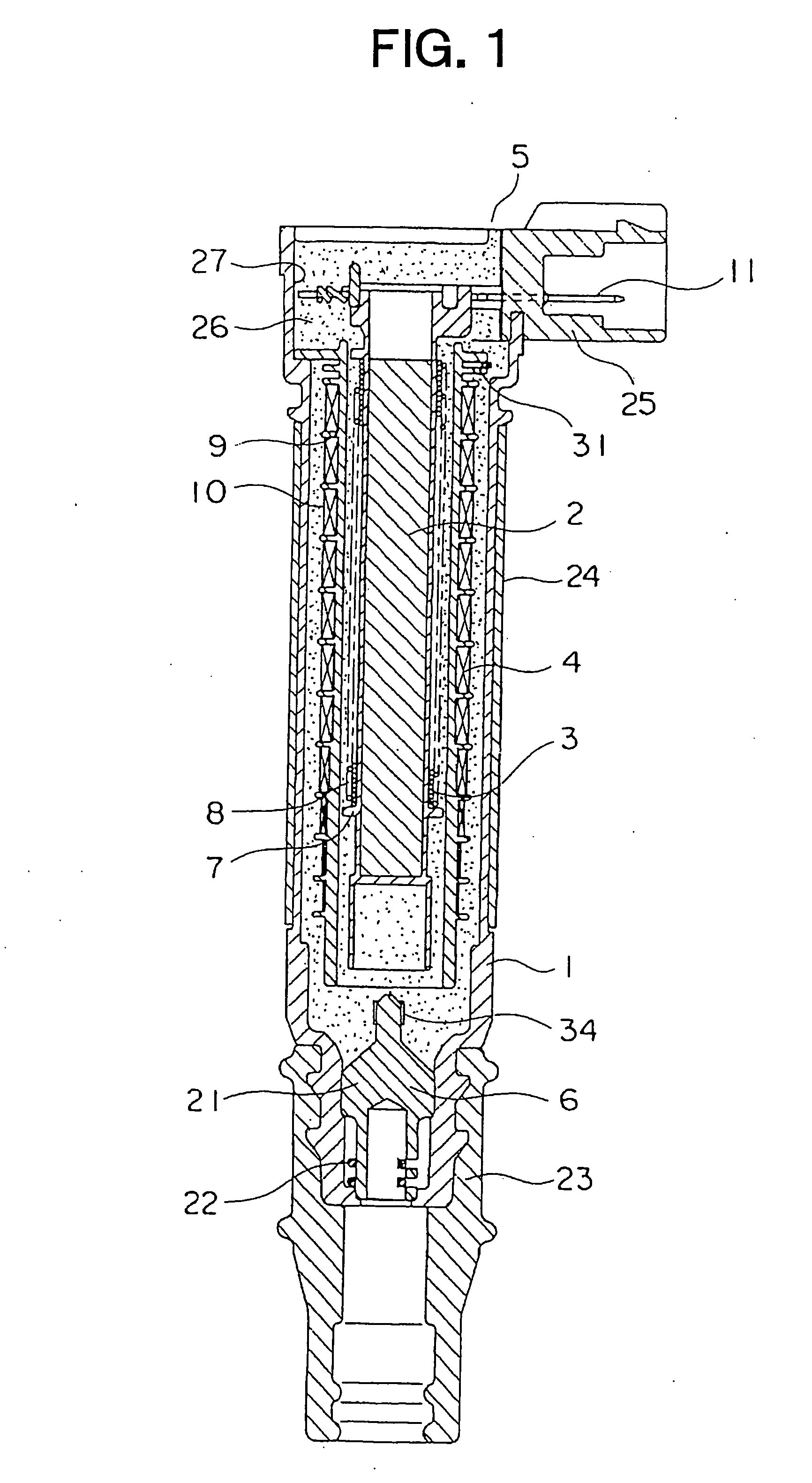
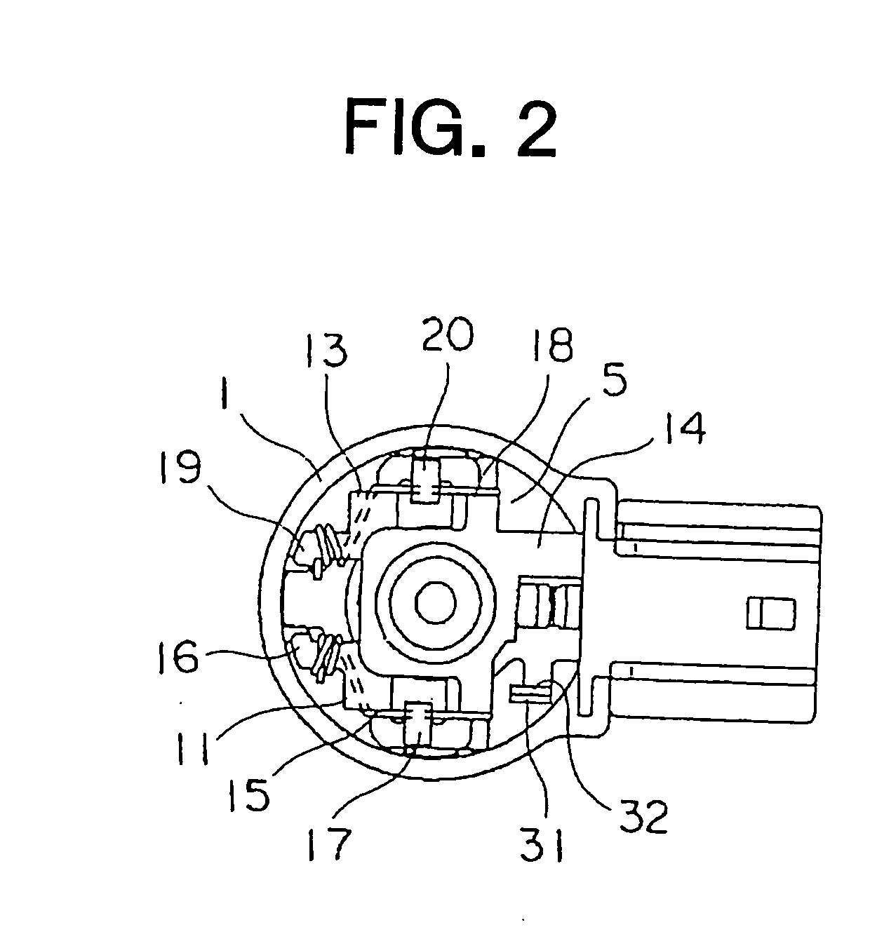
[0025]FIG. 1 is a plan view of an ignition coil apparatus for an internal combustion engine (hereinafter abbreviated as a coil apparatus) according to a first embodiment of the present invention. FIG. 2 is a plan view of the coil apparatus of FIG. 1 with an insulating material being excluded, and FIG. 3 is an electric circuit diagram of the coil apparatus FIG. 1.

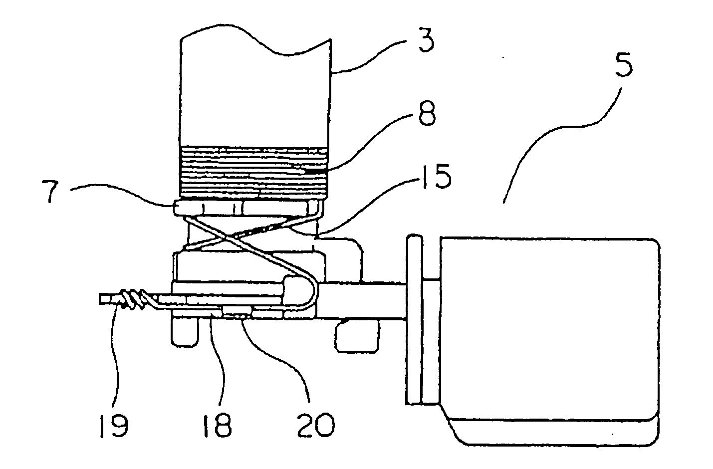
[0026] In this coil apparatus, a column-shaped center core 2 is arranged in in a case 1 of a bottomed cylindrical shape, and the center core extends along and on the central axis of the case 1, and is formed of laminated or stacked strip-shaped silicon steel sheets. A primary coil 3 and a secondary coil 4 are arranged on the outer periphery of this center core 2 in a concentric relation. A low-tension side connector 5 electrically connected to the primary coil 3 is arranged at an upper portion of the case 1, and a high-tension side connector 6 electrically connected to a spark plug (not shown) is arranged at a lower portion...


PUM

PropertyMeasurementUnit
tensionaaaaaaaaaa
radius of curvatureaaaaaaaaaa
diameteraaaaaaaaaa

Abstract

An ignition coil apparatus for an internal combustion engine can suppress an increase in the manufacturing cost of a terminal of a low-tension side connector resulting from variation in a wire diameter of an one end of a primary winding, and can ensure a stable fusing state. The positive terminal side fusing portion is composed of a planar portion and a turned portion that is inversely turned back from the planar portion to cooperate therewith to clamp a winding start conductor portion. A first bent portion of a radius of curvature R is formed at a base end portion of the turned portion. A second bent portion with its tip end tilted toward a planar portion is formed at an intermediate portion of the turned portion.

Description

BACKGROUND OF THE INVENTION [0001] 1. Field of the Invention [0002] The present invention relates to an ignition coil apparatus for an internal combustion engine that is provided with a low-tension side connector whose terminal is electrically connected to an end of a primary winding through fusing. [0003] 2. Description of the Related Art [0004] As an ignition coil apparatus for an internal combustion engine, there has been known one in which a primary winding is electrically connected at its one end to a terminal of a low-tension side connector through a fusing method. [0005] In the case of this ignition coil apparatus for an internal combustion engine, as shown in a first patent document (Japanese patent application laid-open No. 2000-348785) for example, the terminal of the low-tension side connector connected to the one end of the primary winding has a fusing portion turned or bent into a U shape that is formed of a planar portion and a turned portion with its base end portion ...

Claims


Application Information

Patent Timeline
Patent Type & Authority Applications(United States)
IPC IPC(8): H01F27/02
CPCH01F27/2828H01F41/10H01F38/12
Inventor SAWAZAKI, NOBUYUKIUMEZAKI, TOMOKAZU
Owner MITSUBISHI ELECTRIC CORP
Why Eureka
Try Eureka