
Spatial representation assembly

a technology of spatial representation and assembly, which is applied in the direction of optics, instruments, electrical equipment, etc., can solve the problems of inability to consistently high image quality, too expensive in view of industrial quantity production of commonly used rgb lc displays, and inability to meet the requirements of production

Inactive Publication Date: 2006-11-16
X3D TECH GMBH +1
View PDF7 Cites 3 Cited by
  • Summary
  • Abstract
  • Description
  • Claims
  • Application Information

AI Technical Summary

Benefits of technology

[0011] Based on the prior art described, it is the purpose of the present invention to achieve, with few optical components, an autostereoscopic presentation with improved perceptibility, and especially with high brightness.
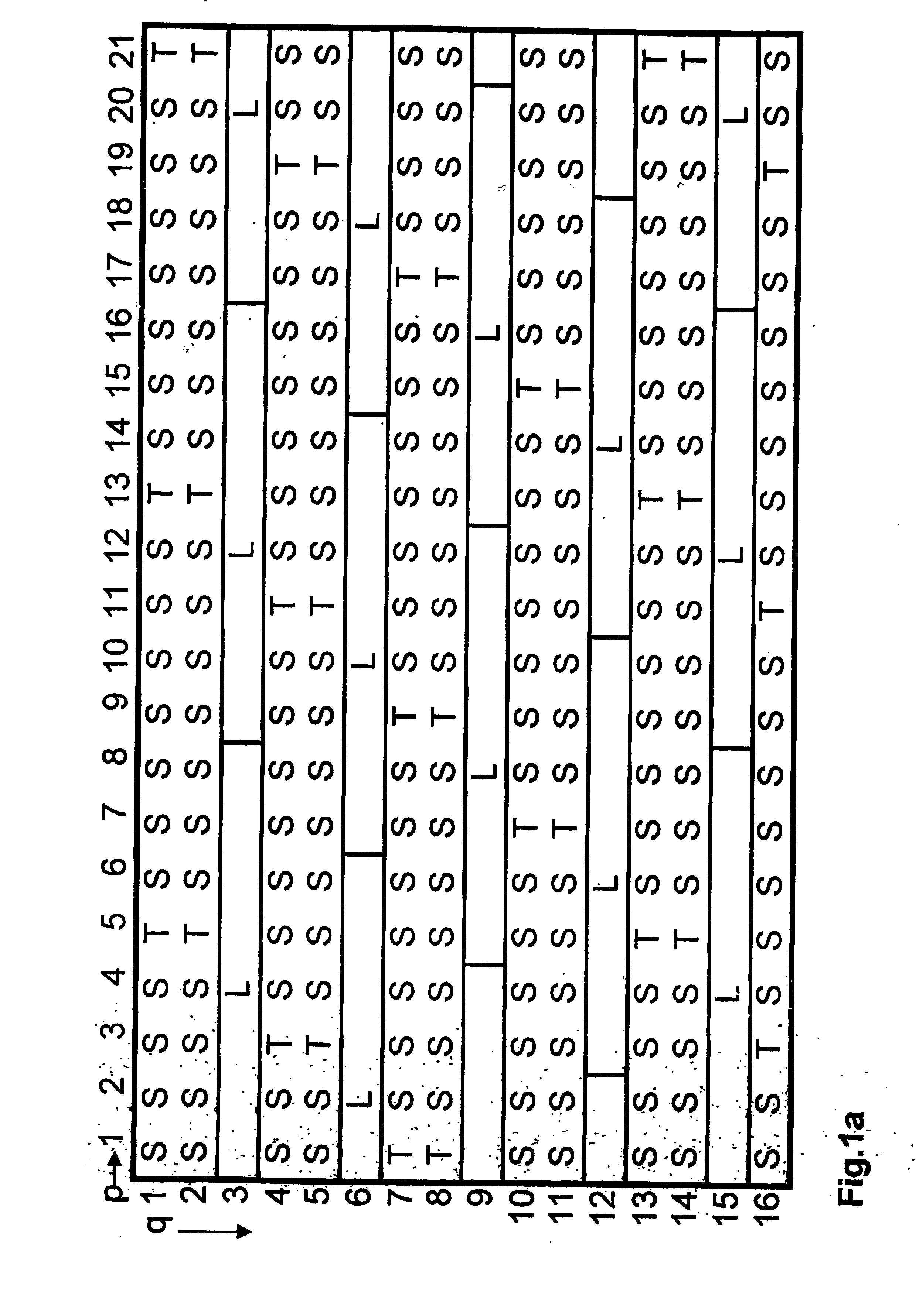
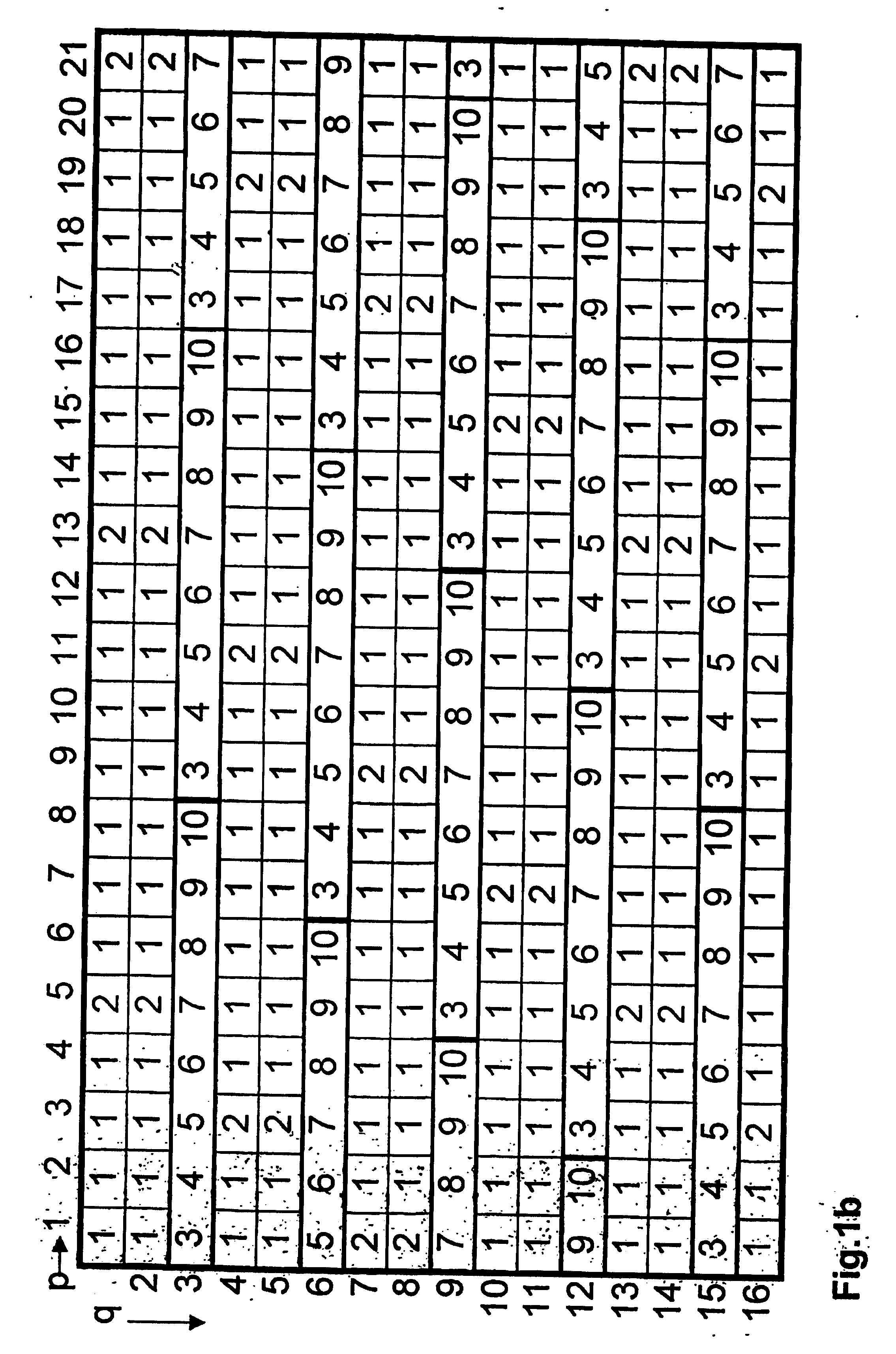
[0019] Due to the structured plate used in it, the method in particular ensures that, with the partial use of lenses, cylinder lenses or prisms, the spatial image seen has a higher brightness than that achieved, for example, with a pure barrier method; and in so far as, at least partially, color or gray level filters are used, a sharply focused 3D image is produced.
[0050] Furthermore, the structured plate may be configured to be detachable from the image display device. Detaching the structured plate from the image display device is advantageous especially if the user wants purely two-dimensional image information or text to be displayed. The detachment of the structured plate from, and its re-attachment to, the image-display device are quasi-equivalent to a switching between 2D and 3D modes and vice versa, respectively.

Problems solved by technology

The implementation of this suggestion involves the disadvantage that alterations to tried-and-approved embodiments and manufacturing processes have to be made, which would be too expensive in view of industrial quantity production of the commonly used RGB LC displays.
Moreover, the measure suggested does not eliminate the disadvantages in the case of two-dimensional presentations, so that there is no consistently high image quality when the arrangement is switched over from autostereoscopic to two-dimensional presentation.
With these arrangements, the unfavorable effects described above also occur.
Inevitably, this means that conventional LC cannot be used to produce the structured illumination, because the subpixel color structure of these displays is of the RGBRGBRGB .
Moreover, the periodically arranged, stripe-shaped wavelength filters inevitably produce moire fringes again.
An added disadvantage is the fixed distance from the image plane specified for the viewer, which derives from the equations and functions given.
The arrangement also has the disadvantages described above, and the same also applies to the arrangement described in JP 8146346, which uses a two-channel method with stripe-shaped wavelength filters for assigning directions to the two perspective views.
The drawback is that the greater brightness achieved by imaging through a lenticular compared to imaging through a barrier is thwarted because of the added barrier extending over the entire rear side of the lenticular.

Method used


Image

  • Spatial representation assembly
  • Spatial representation assembly
  • Spatial representation assembly

Examples


Embodiment Construction

[0011] Based on the prior art described, it is the purpose of the present invention to achieve, with few optical components, an autostereoscopic presentation with improved perceptibility, and especially with high brightness.

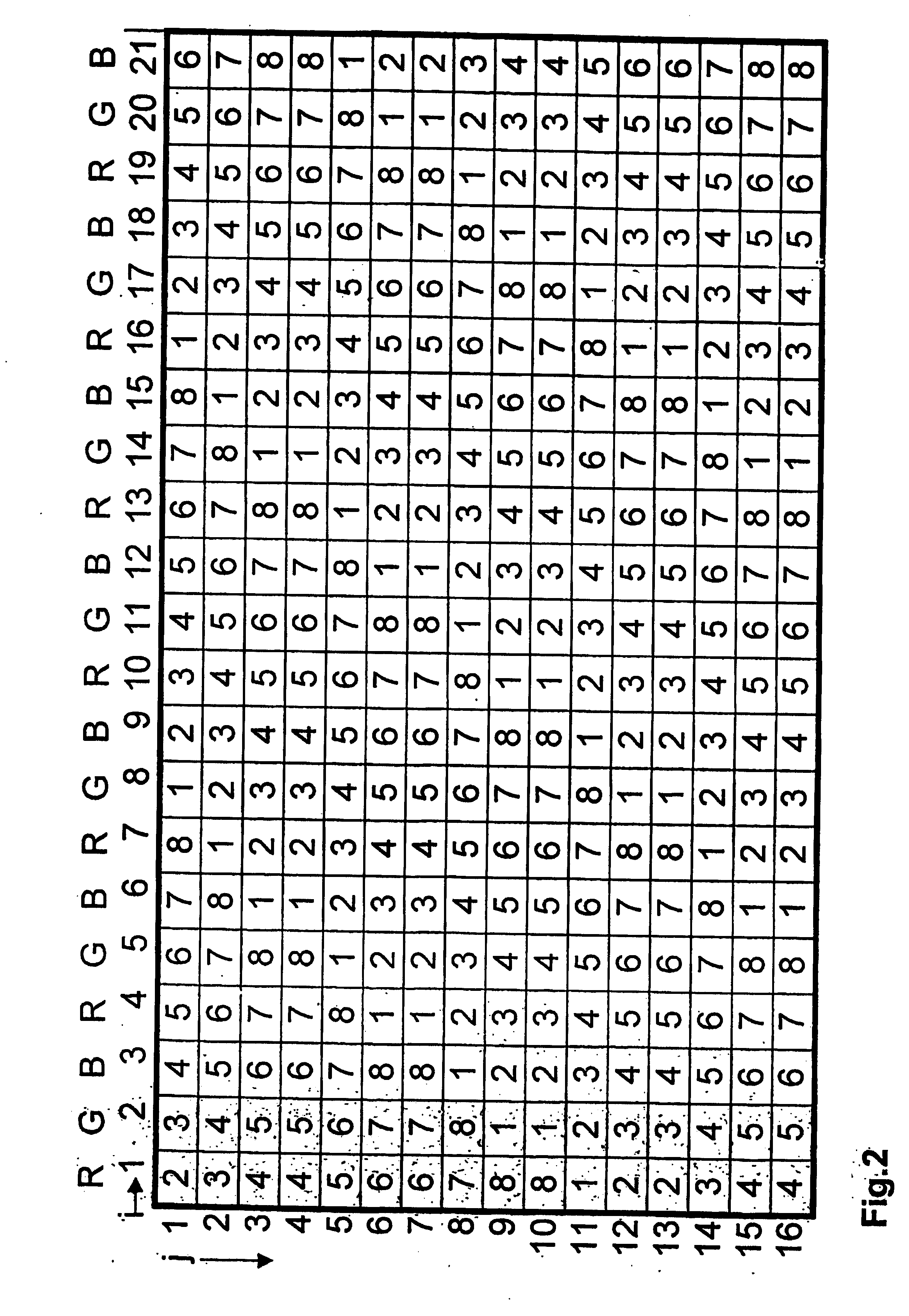
[0012] According to the invention, the problem is solved by an arrangement for spatially displaying a scene or object, [0013] comprising an image display device, on which a great number of individual picture elements (pixels) αij arranged in a grid of rows j and columns i are made visible simultaneously, the said pixels αij rendering bits of partial information from several views Ak (k=1 . . . n, n>1) of the scene or object, [0014] and further comprising a structured plate, arranged in front of or behind the image display device, by means of which propagation directions are established for the light radiated by the pixels αij, [0015] and in which the structured plate contains a great number of optical imaging elements βpq arranged in a grid of rows q and columns...


PUM


Abstract

The invention relates to arrangements for spatially displaying a scene or object, in which a great number of individual pixels αij in a grid of rows (j) and columns (i) are made visible simultaneously, with the pixels (αij) presenting bits of partial information from several views Ak (k=1 . . . n) of the scene or object, and in which propagation directions for the light radiated by the pixels (αij) are established by means of a structured plate. The structured plate contains a great number of optical imaging elements (βpq) arranged in a grid of rows (q) and columns (p). According to the invention, at least two of the following kinds of optical imaging elements (βpq) are simultaneously provided on the structured plate, viz. wavelength or gray level filter, lens or cylinder lens, and / or prism.

Description

FIELD OF THE INVENTION [0001] The invention relates to arrangements for three-dimensional display, especially to such that provide a spatial impression to one or several viewers without any aids such as filter goggles. DESCRIPTION OF PRIOR ART [0002] Efforts to make images of objects, sceneries, views of the interior of bodies and other things appear to a viewer to have three dimensions have, in the course of development, resulted in a great number of autostereoscopic methods. [0003] Some of these methods are based on the principle that several optical views of a scene or object recorded from different angles (“perspective views”), while displayed simultaneously, are separated by suitable means so that either eye of a viewer sees only one of these views, or several but different views, resulting in a parallax effect that makes the image appear spatial. [0004] EP 0791847 describes an arrangement in which autostereoscopic presentations are made by means of an RGB LC display used in co...

Claims


Application Information

Patent Timeline
IPC IPC(8): G02B27/22H04N13/00
CPCH04N13/0454H04N13/0404H04N13/305H04N13/359
Inventor RELKE, INGO
Owner X3D TECH GMBH
Learn More