Variable-shape mirror and optical pickup device therewith

a pickup device and mirror technology, applied in the field of variable mirror shape, can solve the problems of inability to accurately write or read information, method is unsuitable for use in a small component such as an optical pickup device, and not always remain perpendicular, so as to achieve wide mirror shape variation range, prevent deformation, and surely correct aberrations in a wide range.

Inactive Publication Date: 2006-11-16
FUNAI ELECTRIC CO LTD
View PDF26 Cites 5 Cited by
  • Summary
  • Abstract
  • Description
  • Claims
  • Application Information

AI Technical Summary

Benefits of technology

[0011] In view of the conventionally encountered inconveniences discussed above, it is an object of the present invention to provide a variable-shape mirror that can vary the shape of the mirror surface thereof wherein, when the shape of the mirror surface is varied with a piezoelectric element, the mirror surface is prevented from local deformation. It is another object of the present invention to provide a variable-shape mirror that, despite being so structured as to prevent the mirror surface thereof from local deformation, offers a sufficiently wide mirror shape variation range. It is still another object of the present invention to provide an optical pickup device that is provided with a variable-shape mirror of which the mirror surface is prevented from local deformation and that can thus properly correct aberrations in a wide range.
[0013] With this structure, in the variable-shape mirror that can vary the shape of the mirror surface thereof, the piezoelectric element is not bonded to the mirror portion. Thus, even when the piezoelectric element expands or contracts, the mirror surface of the mirror portion is prevented from local deformation due to the piezoelectric element and the mirror portion being bonded together. Moreover, when the piezoelectric element is not operating, the mirror portion receives a predetermined force from the piezoelectric element. Thus, even when the piezoelectric element contracts, the counterforce of the mirror portion can be exploited to hold the contact between the mirror portion and the piezoelectric element and hence to maintain the electrical conduction to the piezoelectric element. Thus, it is possible to obtain a shape variation range of the mirror portion corresponding to the expansion and contraction range of the piezoelectric element just as in a case where the mirror portion and the piezoelectric element are bonded together.
[0021] With this structure, since four piezoelectric elements are provided symmetrically, it is possible to vary the shape of the mirror surface in a well-balanced fashion.
[0023] With this structure, it is possible to prevent the mirror surface of the variable-shape mirror from local deformation, and to obtain a wide mirror shape variation range while preventing deformation. Thus, it is possible to surely correct aberrations in a wide range.

Problems solved by technology

In reality, however, when the disc is rotating, their relationship does not always remain perpendicular.
When coma aberration is produced, the spot of laser light shone on the optical disc deviates from the proper position, and, when the coma aberration becomes larger than permitted, inconveniently, it becomes impossible to accurately write or read information.
Disadvantageously, however, this method is unsuitable for use in a small component such as an optical pickup device because it does not take wiring and other factors into consideration.
Moreover, it is difficult, both technically and in terms of cost, to miniaturize multi-layered piezoelectric elements used as those actuators.
Disadvantageously, however, it is technically rather difficult to provide a sealed space in a variable-shape mirror.
If the mirror surface deforms, it is impossible to correct coma aberration.
Disadvantageously, however, by this method, certainly the adhesive layer can be formed thin, but, since the mirror and the piezoelectric element are bonded together with adhesive, when the shape of the mirror is varied with the piezoelectric element, the mirror surface may locally deform.
When deformation due to the mirror and the piezoelectric element being bonded together occurs, as described above, it is impossible to properly correct coma aberration.
Incidentally, a variable-shape mirror is required to be designed to offer as large a mirror displacement as possible, because, with an insufficient mirror displacement, it is impossible to satisfactorily correct aberrations.

Method used


Image

  • Variable-shape mirror and optical pickup device therewith
  • Variable-shape mirror and optical pickup device therewith
  • Variable-shape mirror and optical pickup device therewith

Examples


Embodiment Construction

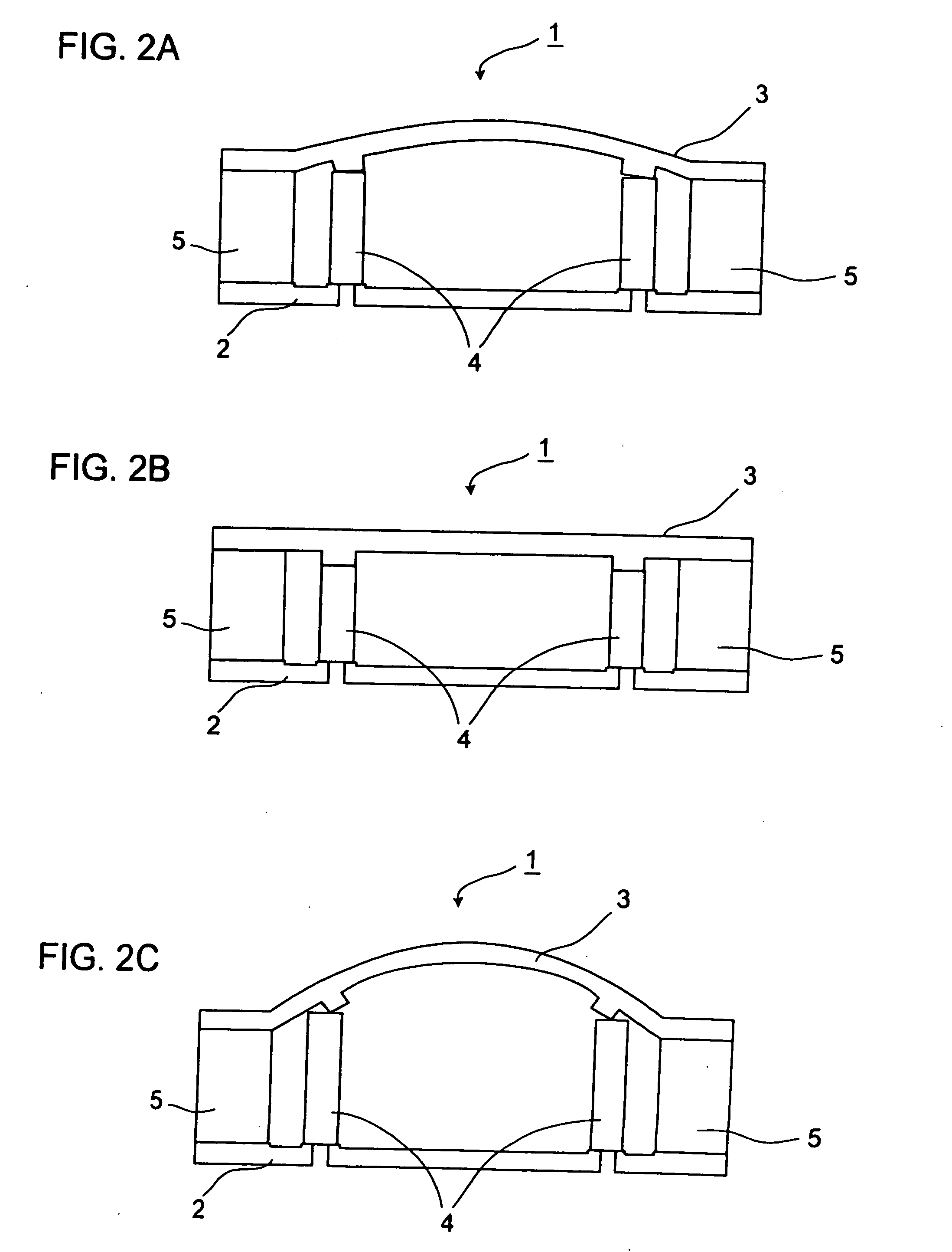
[0039] Hereinafter, embodiments of the present invention will be described with reference to the accompanying drawings. It should be understood that the embodiments described below are merely examples, and are therefore not meant to limit in any way the manner in which the present invention can be carried. It should also be understood that, in the drawings, the sizes and thicknesses of the components, the amount of displacement that takes place when the shape is varied, etc. are exaggerated for the purpose of easy understanding, and therefore these dimensions are different from those actually observed.

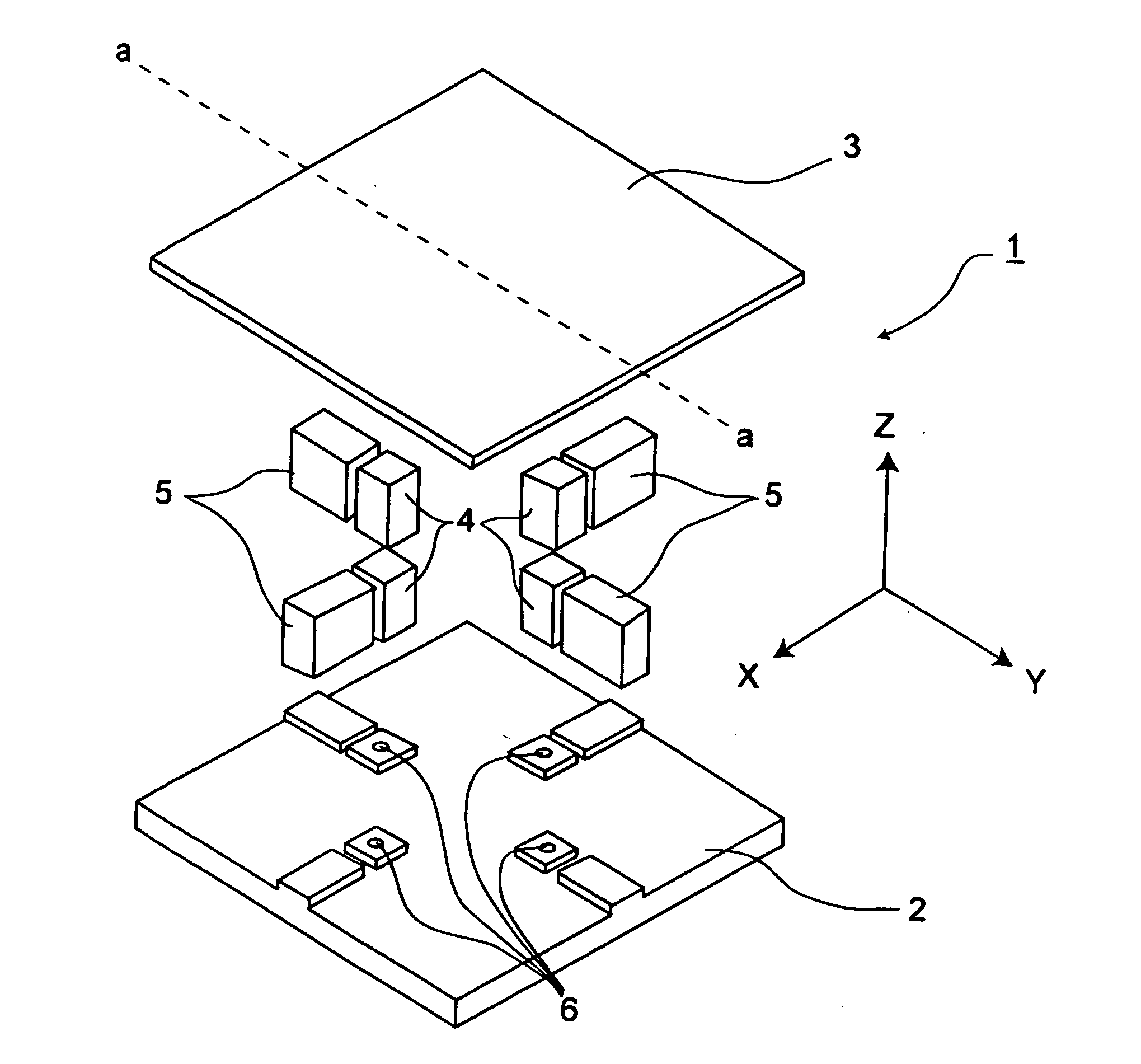
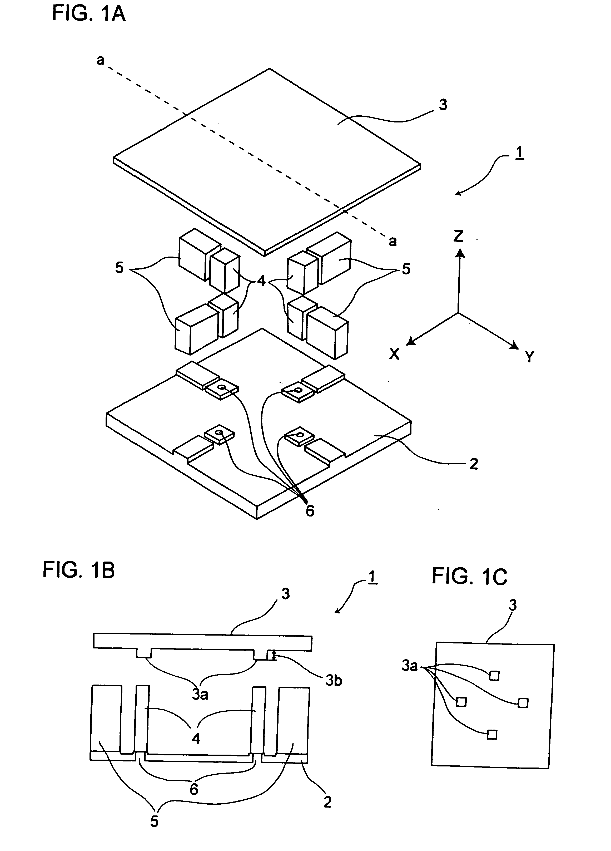
[0040]FIG. 1A is a diagram showing the structure of the variable-shape mirror of a first embodiment of the present invention, showing the components thereof in an exploded perspective view. FIG. 1B is a sectional view cut along line a-a shown in FIG. 1A. FIG. 1C is a front view of the mirror portion of the variable-shape mirror, as seen from behind the mirror surface.

[0041] Reference...


PUM


Abstract

In a variable-shape mirror of which the shape of the mirror surface can be varied, a mirror portion is bonded only to a fixed portion and not to a piezoelectric element. When the piezoelectric element is not operating, the mirror portion, receiving a predetermined force from the piezoelectric element, makes contact with the piezoelectric element. When the piezoelectric element contracts, the mirror portion tends to restore its original shape by its counterforce. Thus, even when the piezoelectric element contracts, the contact between the mirror portion and the piezoelectric element is held, and hence the electric conduction to the piezoelectric element is maintained.

Description

[0001] This application is based on Japanese Patent Application No. 2005-121658 filed on Apr. 19, 2005, the contents of which are hereby incorporated by reference. BACKGROUND OF THE INVENTION [0002] 1. Field of the Invention [0003] The present invention relates to a variable-shape mirror that permits the shape of a mirror surface thereof to be varied, and more particularly relates to prevention of the deformation that occurs when the mirror surface of a variable-shape mirror is varied. The present invention also relates to an optical pickup device provided with a variable-shape mirror of which the mirror surface is prevented from deformation. [0004] 2. Description of Related Art [0005] When information is read from or written to an optical disc such as a CD (compact disc) or DVD (digital versatile disc) by the use of an optical pickup device, the relationship between the optical axis of the optical pickup device and the disc surface should ideally be perpendicular. In reality, howev...

Claims


Application Information

Patent Timeline
Patent Type & Authority Applications(United States)
IPC IPC(8): G02B5/08G02B7/182
CPCG02B26/0825G02B7/1822
Inventor FUJII, HITOSHISUGIYAMA, SUSUMUISHII, AKIRATANAKA, KATSUHIKOKUZE, WATARU
Owner FUNAI ELECTRIC CO LTD
Why Eureka
Try Eureka