Backlight module

a backlight module and module technology, applied in the field of backlight modules, can solve the problems of general unavoidable dark area pluriplication, and achieve the effect of extending the width of the module, and reducing the number of modules

Active Publication Date: 2006-11-16
HON HAI PRECISION IND CO LTD
View PDF5 Cites 39 Cited by
  • Summary
  • Abstract
  • Description
  • Claims
  • Application Information

AI Technical Summary

Benefits of technology

[0012] Compared with conventional backlight modules, a preferred backlight module of the present design has a light source disposed adjacent to the corner of the incident surface of the light guide plate and a reflector disposed adjacent to the light source and substantially covering (i.e., extending the width of) the incident surface. Light beams emitted from the light source are all reflected by the reflector and enter into the light guide plate through the incident surface. There are no light beams that are blocked by the LEDs. Therefore, the dark areas can be effectively eliminated. Therefore, the backlight module has a highly uniform brightness.

Problems solved by technology

However, a plurality of dark areas are generally unavoidably formed adjacent the incident surface 832.

Method used


Image

  • Backlight module
  • Backlight module
  • Backlight module

Examples


Embodiment Construction

[0027] Reference will now be made to the drawings to describe preferred embodiments of the present backlight module, in detail.

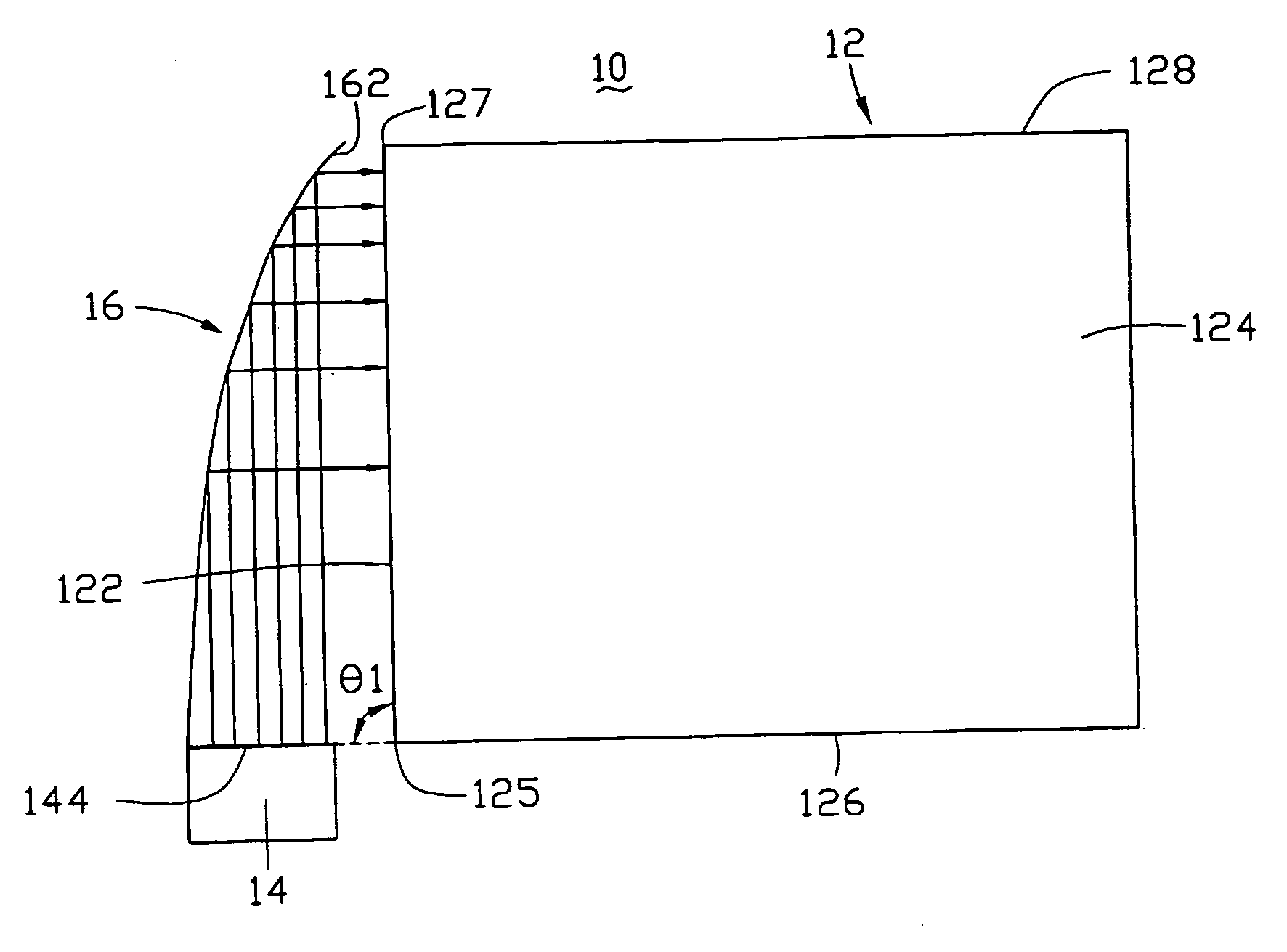
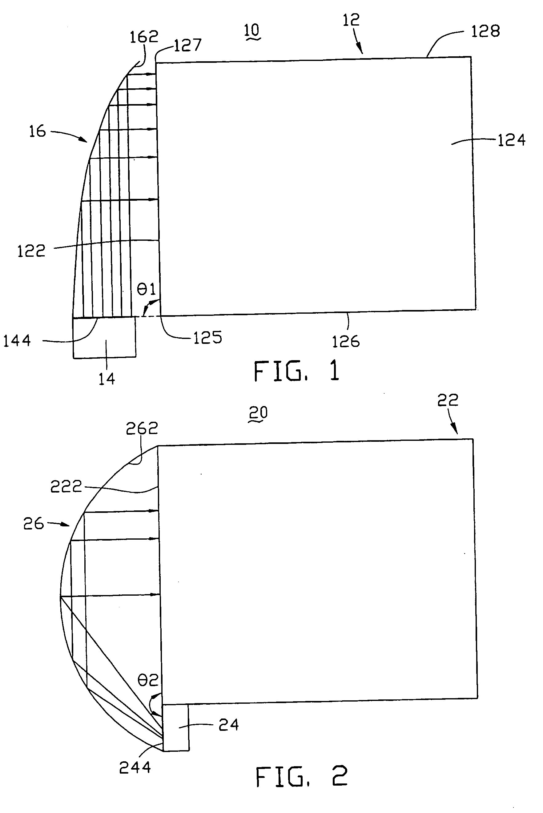
[0028] Referring to FIG. 1, a backlight module 10 in accordance with a first preferred embodiment is shown. The backlight module 10 includes a light guide plate 12, a light emitting diode (LED) 14, and a reflector 16. The light guide plate 12 is generally a flat sheet having a substantially rectangular shape in plan view. The light guide plate 12 includes an incident surface 122, an emitting surface 124, and two main opposite side surfaces 126, 128. The incident surface 122 interconnects the two main opposite side surface 124, 126. The incident surface 122 and the main opposite side surface 124, 126 cooperatively form two corners 125, 127. The emitting surface 124 is the top surface of the light guide plate 12. The LED 14 is disposed adjacent the corner 125. The LED 14 has an emitting surface 144. An angle of inclination θ1 exists between the emitting surfa...


PUM


Abstract

A backlight module includes a light guide plate, a light source, and a reflector. The light guide plate includes an incident surface and a corner adjacent the incident surface. The light source is disposed adjacent the incident surface and the corner of the light guide plate. The light source has an emitting surface. The reflector is disposed substantially facing the incident surface. The reflector has a curved reflective surface facing the emitting surface, the surface being shaped and positioned for uniformly reflecting light beams emitted from the light source into the light guide plate through the incident surface. An angle of inclination of the emitting surface with respect to the incident surface is chosen to be in the range from above about 0 to about 180 degrees. The backlight module can effectively eliminate shadow formation adjacent the incident surface of the light guide plate.

Description

BACKGROUND OF THE INVENTION [0001] 1. Field of the Invention [0002] The present invention relates to a backlight module and, particularly, to an edge-lighting type backlight module for use in, for example, a liquid crystal display (LCD). [0003] 2. Discussion of the Related Art [0004] In a liquid crystal display device, liquid crystal is a substance that does not itself radiate light. Instead, the liquid crystal relies on receiving light from a light source to thereby display images and data. In the case of a typical liquid crystal display device, a backlight module powered by electricity supplies the needed light. [0005]FIG. 8 (Prior art) represents a conventional edge-lighting type backlight module 80. The backlight module 80 includes a plurality of light emitting diodes (LEDs) 81, a light guide plate 83, a diffusion sheet 84, and a prism sheet 85. The light guide plate 83 includes an incident surface 832 and an emitting surface 834 adjacent the incident surface 832. The LEDs 81 ar...

Claims


Application Information

Patent Timeline
Patent Type & Authority Applications(United States)
IPC IPC(8): F21V7/04
CPCG02F1/133615G02B6/0031
Inventor YANG, XING-PENGYAN, YING-BAIJIN, GUO-FAN
Owner HON HAI PRECISION IND CO LTD
Why Eureka
Try Eureka