Surface light source unit and liquid crystal display device with the unit

Inactive Publication Date: 2006-11-16
JAPAN DISPLAY CENT INC
View PDF11 Cites 25 Cited by
  • Summary
  • Abstract
  • Description
  • Claims
  • Application Information

AI Technical Summary

Benefits of technology

[0010] The present invention has been developed in view of the above problem, and aims to provide a surface light source unit, in which a light guide is prevented from contacting the pr

Problems solved by technology

In the prior art, when an external force is applied to the liquid crystal display device, thereby causing the surface light source unit to, for example, be twisted, the light guide may contact the back frame, thereby gener

Method used


Image

  • Surface light source unit and liquid crystal display device with the unit
  • Surface light source unit and liquid crystal display device with the unit
  • Surface light source unit and liquid crystal display device with the unit

Examples


Embodiment Construction

[0020] Referring to the accompanying drawings, a description will be given of a surface light source unit according to an embodiment of the invention, and a liquid crystal display device provided with the surface light source unit.

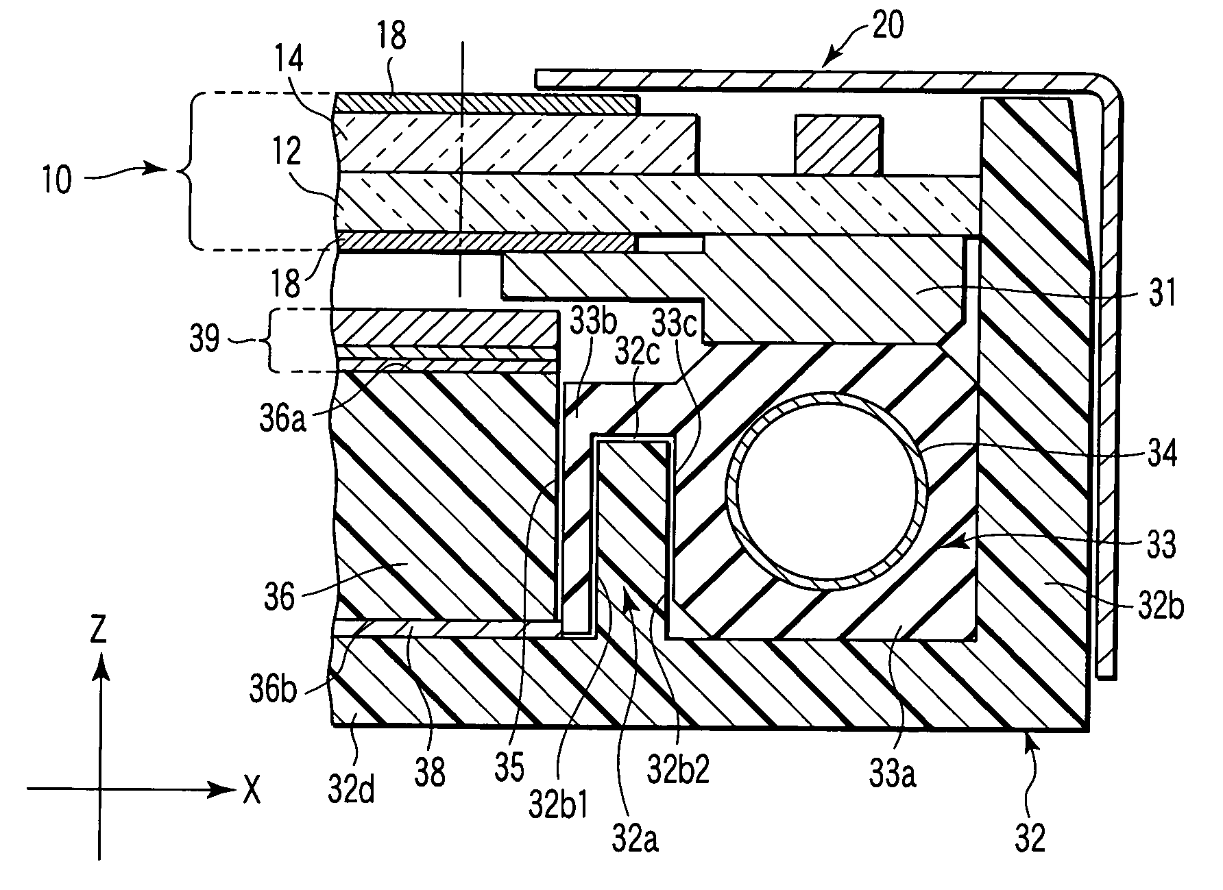
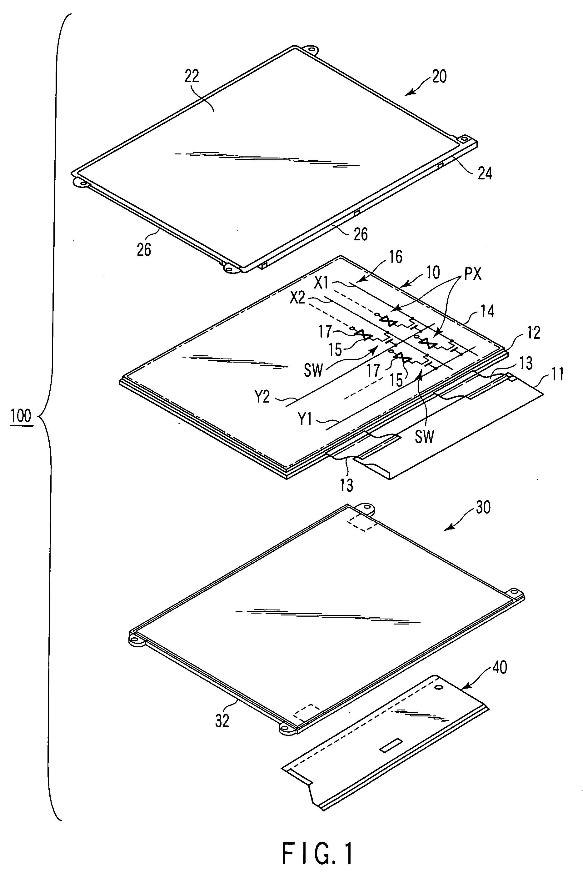
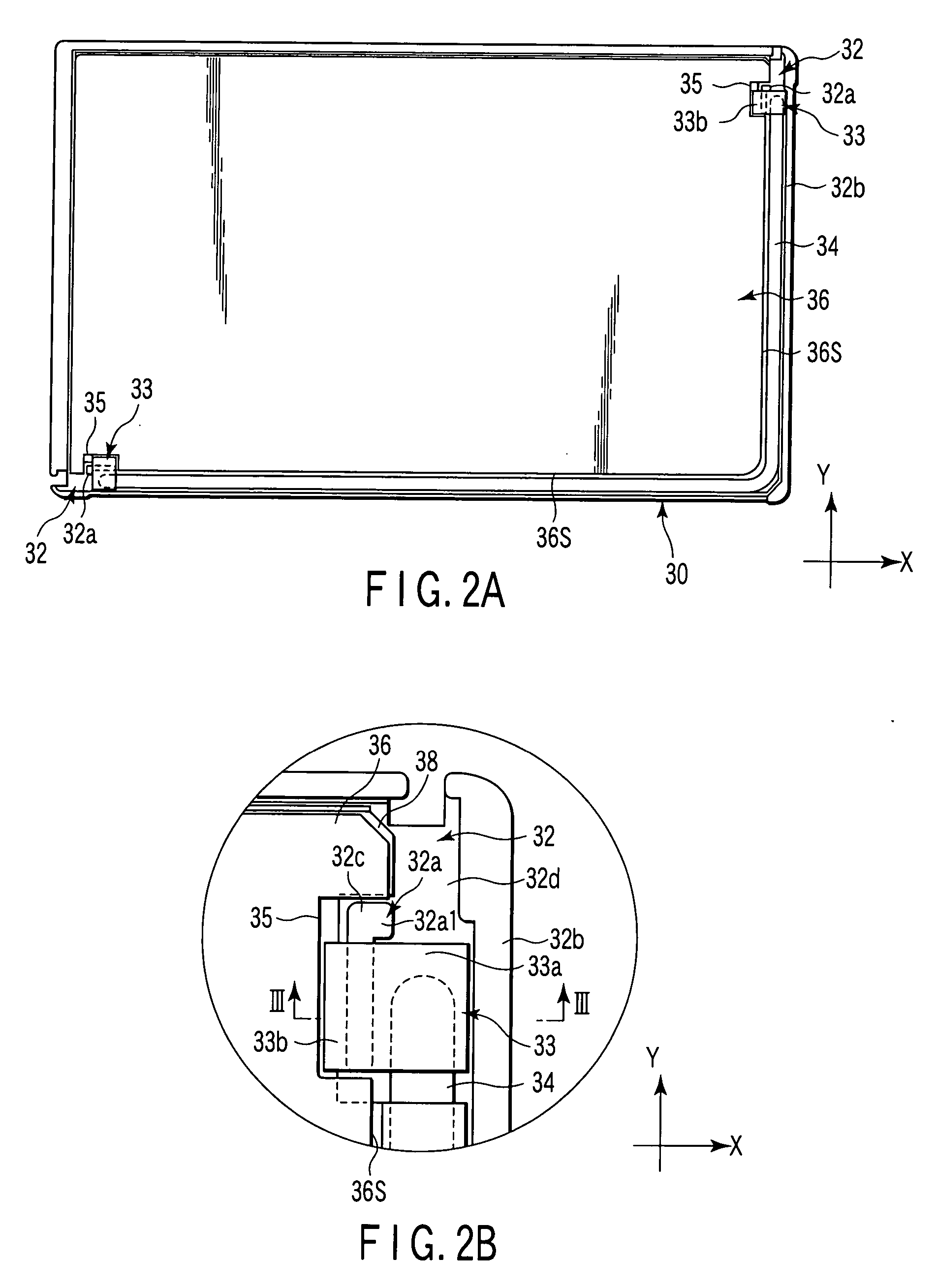
[0021] As shown in FIG. 1, a liquid crystal display device 100 comprises a rectangular liquid crystal display panel 10, a backlight 30 as a surface light source unit for illuminating the panel 10 from behind, and a cover 20 attached to a back frame 32, incorporated in the backlight 30, for holding the periphery of the liquid crystal display device. The backlight 30 is attached to the reverse side of the panel 10. The rectangular-frame-shaped cover 20 is attached to the obverse side of the panel 10.

[0022] As shown in FIGS. 1 and 3, the liquid crystal display panel 10 includes an array substrate 12 and counter substrate 14. A liquid crystal layer is interposed between the substrates 12 and 14. Respective polarizing plates 18 are fixed on the outer surfaces...


PUM


Abstract

A surface light source unit includes a cold-cathode fluorescent tube, a light guide which receives light from the cold-cathode fluorescent tube and outputs the light, a back frame supporting the cold-cathode fluorescent tube and the light guide and including a projection used to position the light guide and the cold-cathode fluorescent tube, and a lamp holder including a holding portion which holds an end of the cold-cathode fluorescent tube, and a buffering portion provided between the projection and the cold-cathode fluorescent tube.

Description

CROSS-REFERENCE TO RELATED APPLICATIONS [0001] This application is based upon and claims the benefit of priority from prior Japanese Patent Application No. 2005-141057, filed May 13, 2005, the entire contents of which are incorporated herein by reference. BACKGROUND OF THE INVENTION [0002] 1. Field of the Invention [0003] The present invention relates to a surface light source unit with a light guide, and a liquid crystal display device with the surface light source unit. [0004] 2. Description of the Related Art [0005] In general, liquid crystal display devices comprise a liquid crystal display panel for displaying an input image, and a surface light source unit for illuminating the panel from behind. The display liquid display panel is supported by the back frame of the surface light source, and has its periphery covered with a cover. [0006] The surface light source unit includes a light source for emitting light, and a light guide for guiding the light emitted from the light sourc...

Claims


Application Information

Patent Timeline
IPC IPC(8): F21V7/04
CPCG02B6/0071G02B6/0091G02F2201/503G02F2001/133314G02F1/133308G02F1/133314G02F1/1335
Inventor SHIMIZU, MAKOTOURA, TOSHIHIKOYASUDA, YOSHINORIKANEDA, HIROMI
Owner JAPAN DISPLAY CENT INC
Why Eureka
Try Eureka