Multi-channel scheduling method for WLAN devices with a single radio interface

a multi-channel scheduling and radio interface technology, applied in the field of multi-channel scheduling methods for wireless local area network (wlan) devices with a single radio interface, can solve the problems of unintended functions, undesirable that the beacon period be used to enable multi-channel operation, and relatively long beacon period, so as to achieve optimal multicast/broadcast

Active Publication Date: 2006-11-16
SAMSUNG ELECTRONICS CO LTD
View PDF8 Cites 31 Cited by
  • Summary
  • Abstract
  • Description
  • Claims
  • Application Information

AI Technical Summary

Benefits of technology

[0014] It is, therefore, an object of exemplary embodiments of the present invention to provide a multi-channel scheduling method that can enable communication between arbitrary Mesh Points (MPs) operating on multiple channels in relation to a node with a single radio interface, multiplex a Basic Service Set (BSS) and Wireless Distribution System (WDS) traffic, and optimize multicast / broadcast.

Problems solved by technology

Using the beacon period, the conventional method has three problems.
First, an unintended function is included due to the beacon period.
Accordingly, it is undesirable for that the beacon period to be used to enable multi-channel operation.
The beacon period is a relatively long time.
When traffic to be communicated to a WLAN device on the same channel is insufficient during this time, radio resource waste and an unnecessary delay time may occur.
Second, a multi-hop environment, such as recent mesh networking, is not supported because the beacon period has been designed for a single-hop environment in which all WLAN devices can communicate with each other.
Third, when an MP supports communication with a station (STA) through an Access Point (AP) function, synchronization based on the beacon period with other MPs is not allowed because of beacon collision.

Method used


Image

  • Multi-channel scheduling method for WLAN devices with a single radio interface
  • Multi-channel scheduling method for WLAN devices with a single radio interface
  • Multi-channel scheduling method for WLAN devices with a single radio interface

Examples


Embodiment Construction

[0025] The matters exemplified in this description are provided to assist in a comprehensive understanding of various exemplary embodiments of the present invention disclosed with reference to the accompanying figures. Accordingly, those of ordinary skill in the art will recognize that various changes and modifications of the exemplary embodiments described herein can be made without departing from the scope and spirit of the claimed invention. Descriptions of well-known functions and constructions are omitted for clarity and conciseness.

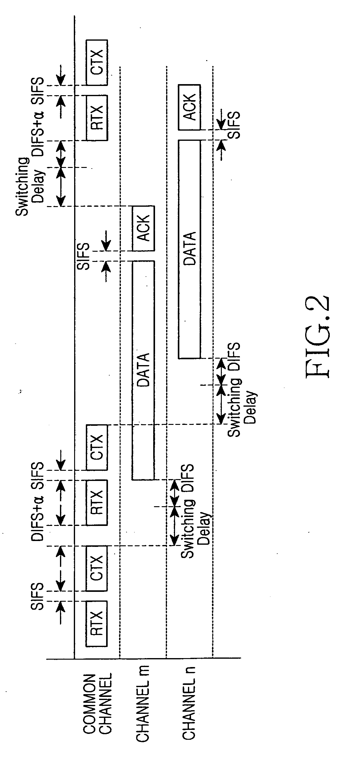
[0026]FIG. 2 schematically illustrates dynamic channel selection on a common channel in accordance with an exemplary embodiment of the present invention.

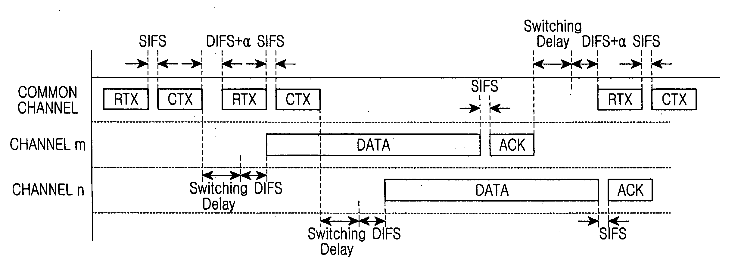
[0027] Referring to FIG. 2, a Mesh Point (MP) capable of communicating with other MPs can exploit a common channel to select an available channel. This is the core of a dynamic channel selection scheme. Information about a target channel m is exchanged in the common channel using Request To Switch...


PUM


Abstract

A multi-channel scheduling method in a wireless network is provided. The wireless network includes a plurality of Wireless Local Area Network (WLAN) devices with a single radio interface. A regular time interval P and a Channel Coordination Window (CCW) to be repeated in a period of P are set. A request is made such that the plurality of devices are tuned to a first channel at a start point of the CCW. A pair of arbitrary WLAN devices among the plurality of WLAN devices is allowed to transmit control frames in the regular time interval P. The control frames are a transmission proposal control frame for proposing communication in a second channel and a response frame, responding to the transmission proposal control frame, for indicating whether the second channel has been accepted or rejected. The arbitrary WLAN devices of the pair are switched to the second channel after acceptance.

Description

CROSS-REFERENCE TO RELATED APPLICATIONS [0001] This application claims the benefit under 35 U.S.C. § 119(e) of U.S. Provisional Application No. 60 / 680,533, filed May 13, 2005, in the United States Patent and Trademark Office, and the benefit under 35 U.S.C. § 119(a) of Korean Patent Application No. 2006-40049, filed May 3, 2006, in the Korean Intellectual Property Office, the entire contents of both of which are hereby incorporated by reference.BACKGROUND OF THE INVENTION [0002] 1. Field of the Invention [0003] The present invention relates to a multi-channel scheduling method for Wireless Local Area Network (WLAN) devices with a single radio interface. More particularly, the present invention relates to a multi-channel scheduling method for WLAN devices with a single radio interface in which various settings are freely performed independent of a beacon period. [0004] 2. Description of the Related Art [0005] A single radio interface is an independent Institute for Electrical and Ele...

Claims


Application Information

Patent Timeline
Patent Type & Authority Applications(United States)
IPC IPC(8): H04B7/005H04Q7/00H04L12/413H04W74/08
CPCH04W74/0866H04W74/002H04W40/244
Inventor LEE, SUNG-WONLEE, JUN-SEOTAORI, RAKESH
Owner SAMSUNG ELECTRONICS CO LTD
Why Eureka
Try Eureka