Wireless reflective marker with internal light source

a technology of reflective markers and light sources, applied in road signs, roads, construction, etc., can solve the problems of reducing the visibility of reflectors, reducing the capability of retroreflectors at distances, and devices involving external wiring, and achieve cost-effective effects

Inactive Publication Date: 2006-11-16
HYE LITES INDS
View PDF22 Cites 8 Cited by
  • Summary
  • Abstract
  • Description
  • Claims
  • Application Information

AI Technical Summary

Benefits of technology

[0005] The present invention overcomes some drawbacks of previous systems. As will become evident below, the present invention can provide a marker with a light source that fits into the standard castings currently in roadways and airport runways. The present invention can provide a cost effective replacement for markers currently installed in pavement such as roadways and airport runways without the need to core the pavement to install each marker. The present invention can provide a replacement to the current markers and can provide a light source in addition to a reflective surface.
[0006] In some embodiments, the present invention provides the same conspicuity as currently used markers and also includes a light source that provides increased conspicuity. Additionally, the present invention can be sized to fit within standard sized steel castings to hold the device generally securely, providing some protection from snow plows and other vehicular traffic. Pre-existing tooling is in place for sawing and attaching these castings to pavement providing low cost installation in the applications described. Still further, in some embodiments the present invention is totally sealed with no wires exiting the enclosed device, simplifying the mounting and improving the reliability with diminished chance for moisture ingress into the device.
[0007] In some embodiments, the present invention uses components to optimize the “on” time of the internal light source while maintaining a low cost. The invention can include solar collectors and batteries to provide long running time for the LED. In addition, some embodiments include regulator circuitry which can provide steady, low current to the LEDs to prolong light output. In some embodiments batteries can be charged from circuits that help maximize their life by not charging or discharging at temperatures below their operating range. Components can be enclosed in sturdy housings capable of mounting in standard castings to hold up well against snow plows, aircraft, or trucks.

Problems solved by technology

However, lights on aircraft in particular and automobiles to some extent may be fairly distant from the vehicle operator, reducing the visibility of the reflector.
In addition, where a roadway turns, retroreflectors have diminished capabilities at distances due to the angle of the approaching light.
However, these devices involve external wiring and cannot fit into existing castings in roadways and runways.
Devices with light sources that do not fit within the recess of a standard casting are not as useful as markers with light sources that can be placed in the standard casting's recess.

Method used


Image

  • Wireless reflective marker with internal light source
  • Wireless reflective marker with internal light source
  • Wireless reflective marker with internal light source

Examples


example

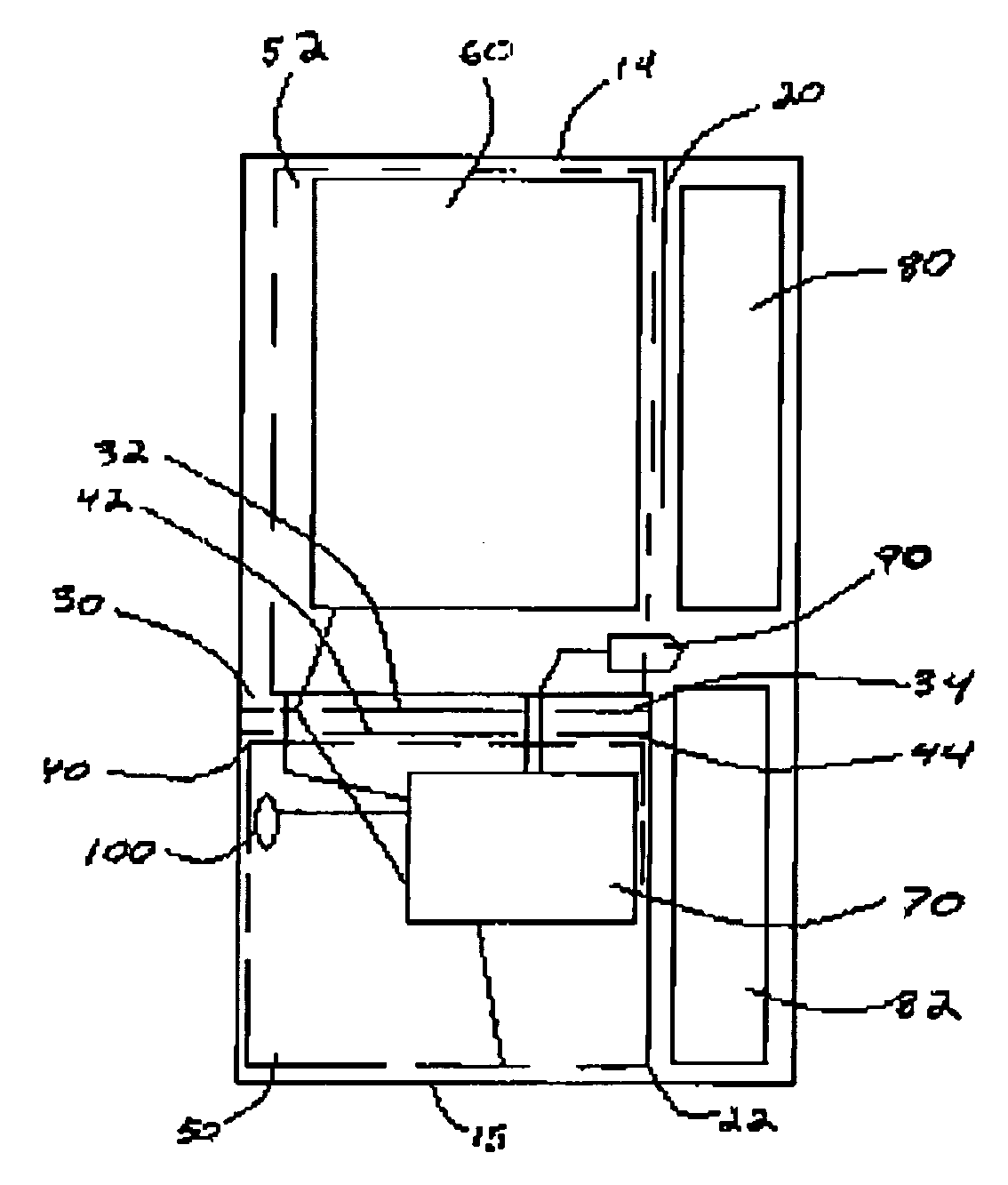
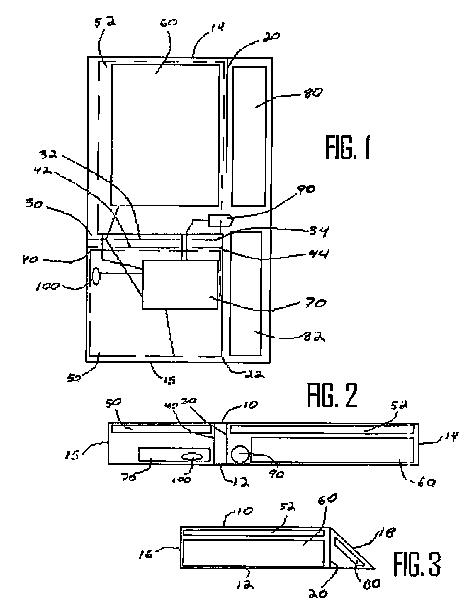
[0048] In an example of an embodiment of the invention, shown in FIGS. 1-3, the front face 18 of a marker 5 is at a diagonal from the horizontal. In an embodiment the angle of the front face is 20-40 degrees from horizontal. The front face 18 has a width of no more than approximately 4 inches and preferably approximately 4 inches. The front face 18 has a length of approximately 12 / 16- 14 / 16 of an inch and preferably approximately 13 / 16 of an inch. The top face 10 and the bottom face 12 of a marker are generally horizontal and parallel to each other. The top face 10 and bottom face 12 each have a width between side faces 14 and 15 of no more than approximately 4 inches and preferably approximately 3¾-4 inches. The bottom face 12 has a width of no more than approximately 2 inches and preferably approximately 1⅞-2 inches. The top face 10 has a width of no more than approximately 1⅜ inch and preferably approximately 1¼-1⅜ inch. Side faces 14 and 15 of a marker are generally horizontal a...


PUM


Abstract

A marker for indicating boundaries or delineating traffic lanes in pavement such as roadways or airport runways is described. In an embodiment, the marker includes a high-strength plastic housing containing at least one retroreflective reflector, a light emitting diode (LED), at least one solar collector and a rechargeable battery. The retroreflective reflectors reflect light back to a light source, such as the headlights of a vehicle on a roadway or the light of an airplane on a runway. The LED can provide a light source that can be seen from greater viewing angles than the light reflected by the reflectors providing better visibility to operators of vehicles on curved roadways and allowing captains of airplanes to see the markers from the cockpit at closer range than if the markers used reflectors alone. In an embodiment, the marker also can include circuitry that controls the operation of the LED, the flow of current through the circuit and the charging of the battery.

Description

FIELD OF THE INVENTION [0001] The present invention relates generally to markers with reflectors and internal lights for use as boundary, obstruction, or hazard indicators in pavement, on fences, or otherwise placed to provide conspicuity to drivers, pilots and others. BACKGROUND OF THE INVENTION [0002] It is a common practice that roadways and airport runways use reflectors to provide improved conspicuity when compared to painted lines, particularly at night and in bad weather. These reflectors are often made of retroreflective elements which return light reflected back toward the light source as opposed to refracting the light as a mirror might. However, lights on aircraft in particular and automobiles to some extent may be fairly distant from the vehicle operator, reducing the visibility of the reflector. In addition, where a roadway turns, retroreflectors have diminished capabilities at distances due to the angle of the approaching light. [0003] Devices with reflectors and light...

Claims


Application Information

Patent Timeline
Patent Type & Authority Applications(United States)
IPC IPC(8): E01F9/06
CPCE01F9/06E01F9/553
Inventor MATIOSIAN, JACOBCAMPION, TIMOTHY M.TALAMO, JOHN A.EIKELBERGER, RAND J.PICKARD, CAREY
Owner HYE LITES INDS
Why Eureka
Try Eureka