
Method and device for determining an angular position signal of an internal combustion

a technology of angular position and engine speed, which is applied in the direction of electrical control, process and machine control, instruments, etc., can solve the problems of reducing the continued use of the rotational-speed signal, and affecting the operation of the engin

Inactive Publication Date: 2006-11-16
ROBERT BOSCH GMBH
View PDF3 Cites 5 Cited by
  • Summary
  • Abstract
  • Description
  • Claims
  • Application Information

AI Technical Summary

Problems solved by technology

The sensing wheels typically have tolerance-related geometric errors and installation faults.
These faults cause a systematic error that substantially degrades the continued use of the rotational-speed signal and, in some circumstances, even renders it unusable for certain functionalities.
The method is based on the fact that the rotational non-uniformity of the internal-combustion engine only has the frequency components mentioned previously.
Even when a series-production combustion chamber pressure sensor does become available, it is not always possible to indicate all cylinders in an engine, due to reasons of cost and limitations on installation space.

Method used


Image

  • Method and device for determining an angular position signal of an internal combustion
  • Method and device for determining an angular position signal of an internal combustion
  • Method and device for determining an angular position signal of an internal combustion

Examples


Embodiment Construction

[0026] The present invention is explained as an example in the exemplary embodiments below.

[0027] As mentioned initially, modern systems for gasoline and diesel engines enable access to the fuel and air path on a cylinder-specific basis. To fully utilize the potential available to reduce fuel consumption and emissions, the engine management system must receive feedback on the processes that are actually taking place in the combustion chamber. The course of pressure in the combustion chamber over time is a key quantity used to realize functionalities of cylinder-specific engine management and control. Even when a series-production combustion chamber pressure sensor does become available, it is not always possible to indicate all cylinders in an engine, due to reasons of cost and limitations on installation space. The present invention was preceded by tests carried out to determine whether the desired combustion-relevant pressure features could be ascertained with the required level ...


PUM


Abstract

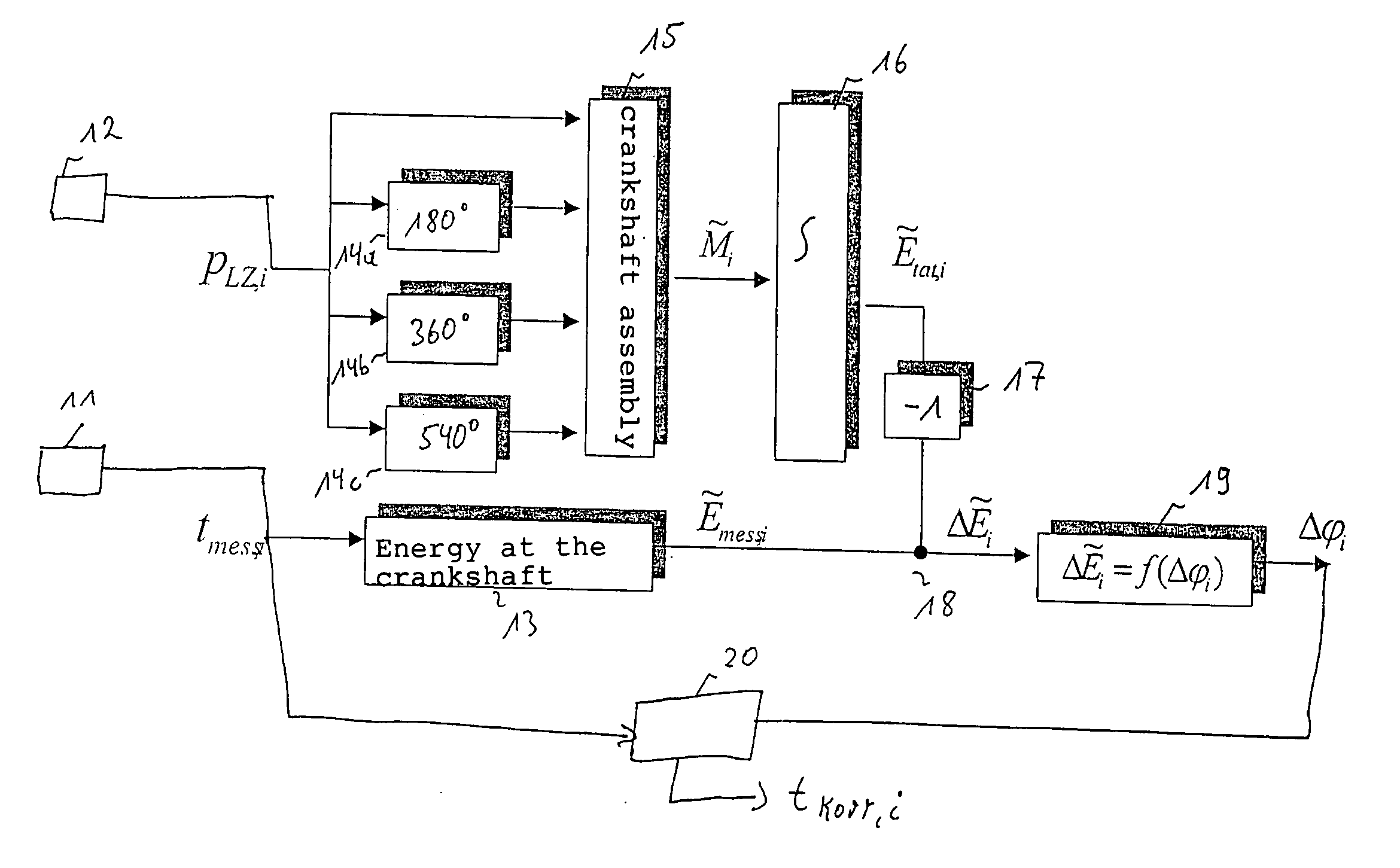
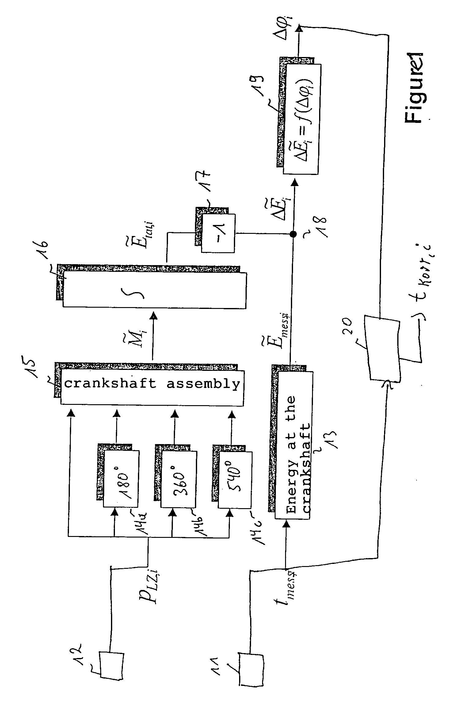
The present invention relates to a method for detecting an angular position signal representing the rotary motion of a rotating part of an internal-combustion engine. The internal-combustion engine includes at least one combustion chamber. In addition, a speed sensor of the type mentioned initially is provided, the speed sensor outputting a rotation-measurement signal representing the rotary motion of a sensing wheel connected with the rotating part. At least one pressure sensor is also provided that outputs a pressure signal representing the pressure in a combustion chamber. The method according to the present invention has the following steps: Detect the pressure signal, detect the rotation-measurement signal, calculate a correction quantity that is a function, at the least, of the detected pressure signal and rotation-measurement signal, and determine the angular position signal by linking the detected rotation-measurement signal with the correction quantity. The core of the present invention is the identification and very good compensation of the sensing wheel error by performing a joint evaluation of the rotational-speed signal and the compression chamber pressure of one or more indicated cylinders.

Description

RELATED ART [0001] The present invention relates to a method and a device for detecting an engine speed signal having the features of the independent claims. [0002] With modern internal-combustion engines, the rotational-speed signal delivers information of key importance to engine management, diagnosis and optimization with regard for various criteria. According to the related art, engine speed is measured with the aid of a sensing wheel mounted on the crankshaft, the sensing wheel having a certain number of markings. The individual markings or increments are detected by a sensor. [0003] The sensing wheels typically have tolerance-related geometric errors and installation faults. These faults cause a systematic error that substantially degrades the continued use of the rotational-speed signal and, in some circumstances, even renders it unusable for certain functionalities. It is therefore crucial that these faults be identified and compensated for. [0004] A number of methods are kn...

Claims


Application Information

Patent Timeline
Patent Type & Authority Applications(United States)
IPC IPC(8): G01M15/05F02D35/02F02D41/00F02D41/14F02D41/34G01D5/244G01M15/06
CPCF02D35/023F02D35/024F02D41/009G01M15/08G01D5/2449G01M15/06G01D5/24452F02D41/008F02D41/0097F02D41/1497G01D18/001
Inventor RAICHLE, FRANZ
Owner ROBERT BOSCH GMBH
Learn More