Eureka AIR delivers breakthrough ideas for toughest innovation challenges, trusted by R&D personnel around the world.

Apparatus for adjustable bead retention on bracelets and necklaces

a technology of adjustable beads and beads, which is applied in the field of bracelets and necklaces, can solve the problems of unlikely unintended movement of the adjustable beads, and achieve the effects of reducing the cost of fabricating the beads, increasing friction, and high surface tension

Inactive Publication Date: 2006-11-23
CHAMILIA
View PDF41 Cites 21 Cited by
  • Summary
  • Abstract
  • Description
  • Claims
  • Application Information

AI Technical Summary

Benefits of technology

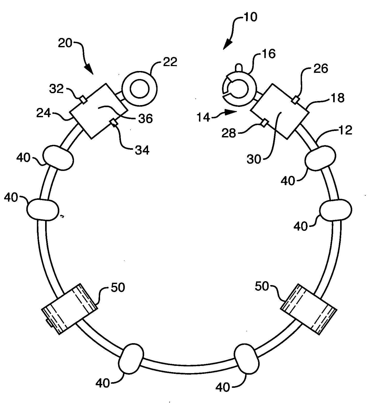
[0012] It is an object of the present invention to provide a modifiable bracelet, necklace, or other removable jewelry item configured to enable a wearer to easily add and remove supplemental pieces to the item strand. It is also an object of the present invention to provide such a modifiable jewelry item configured to enable a wearer to position selectively on the strand one or more retainers to retain one or more supplemental pieces on the strand. Further, it is an object of the present invention to provide such a modifiable jewelry item including end connectors suitable for ease of passage of retainers and / or supplemental pieces thereover.
[0013] These and other objects are achieved with the present invention, which is a modifiable jewelry item including one or more adjustable retainers. The adjustable retainer may be a unitary piece configured to slide onto the strand, chain, or band of the jewelry item. Alternatively, the adjustable retainer may be formed of two parts, possibly hinged, and arranged to be placed about the strand and removably clasped in place thereon. The adjustable retainer of the jewelry item includes an interior structure that keeps the retainer in a selectable position on the strand.
[0015] The interior structure of the adjustable strand may be formed of a viscoelastic material with high surface tension, or it may be a metallic or nonmetallic material with rough surface characteristics. The interior structure may also be formed with one or more grabbing elements, such as hooks, pins, springs, or the like, but not limited thereto, that may grab the outer surface of the strand. Additionally, the outer surface of the strand may be formed with rough surface characteristics and / or grabbing elements to increase the friction between that surface and the interior structure of the adjustable retainer. Alternatively, the strand may be relatively smooth, with the frictional contact provided primarily by the interior structure of the adjustable retainer.
[0016] The arrangement of the retainer including an interior structure designed to establish frictional contact with the outer surface of the strand enables fabrication of a strand without special need for a fixed component designed to engage the retainer. As a result, the cost to fabricate the strand may be reduced. Further, the retainer may be positioned wherever desired along the length of the strand and is not limited to a few locations defined by placement of the fixed component. This enables the wearer to position beads anywhere of interest along the strand and in any combinations. Still further, the retainer preferably fits relatively snugly thereby avoiding loose play on the strand. The retainer is also easily placeable on the strand, eliminating the effort required to screw the retainer over and on fixed elements and end connectors.
[0017] The modifiable jewelry of the present invention further includes one or two convenient end connectors. The end connector or connectors of the modifiable jewelry of the present invention include a body with one or more slots arranged thereon. The body of the end connector is preferably sized to have an exterior dimension or dimensions less than the dimension or dimensions of the interior ports of one or more beads to be positioned on the strand, band, or chain of the jewelry item. In particular, the connector body may have a smaller exterior dimension and a larger exterior dimension, both sized to enable bead ports to pass thereover, but only when the bead and end connector are aligned in a particular way. The bead cannot passed over the end connector without the required alignment. This arrangement eliminates the time consumption associated with screwing a bead over an end connector, but ensures that the end connector will capture the bead on the strand.
[0018] The modifiable jewelry of the present invention, including either or both of the adjustable retainer and the convenient end connectors, is an improvement over existing related jewelry. The improvements provide the wearer with more options and less difficulty in creating customized jewelry arrangements. These and other advantages and features of the invention will become more apparent upon review of the following detailed description, the accompanying drawings, and the appended claims.

Problems solved by technology

Alternatively, the interior structure may be arranged to allow relative ease of movement along the strand, but with enough friction that unintended movement of the adjustable retainer is unlikely to occur.

Method used


Image

  • Apparatus for adjustable bead retention on bracelets and necklaces
  • Apparatus for adjustable bead retention on bracelets and necklaces
  • Apparatus for adjustable bead retention on bracelets and necklaces

Examples


first embodiment

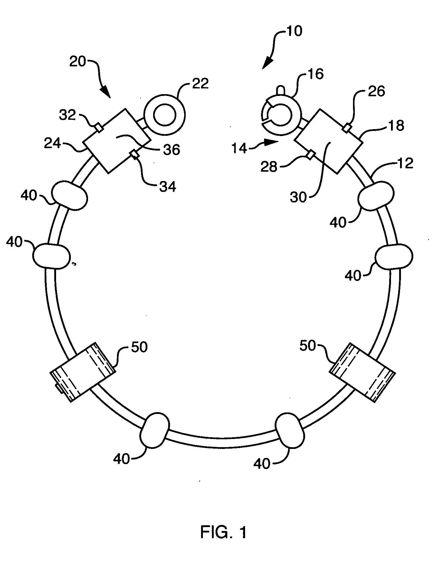
[0032] As illustrated in FIG. 2, the adjustable retainer 50 is a unitary annular ring or bushing fabricated of a selectable material. The unitary adjustable retainer 50 includes an interior structure 52 that may cover a portion or substantially all of the inside dimensions of the adjustable retainer 50. The interior structure 52 is configured to enhance frictional contact between the adjustable retainer 50 and the outer surface of the strand 12. The interior structure may be configured with selectable frictional characteristics. That is, it may be formed to make movement of the adjustable retainer 50 on the strand 12 relatively difficult or relatively simple. A relatively high coefficient of friction of the interior structure 52 makes movement of the adjustable retainer 50 on the strand 12 relatively difficult and would be useful to the wearer who wishes to have little unintended movement of the adjustable retainer 50 on the strand 12. A relatively low coefficient of friction of the...

second embodiment

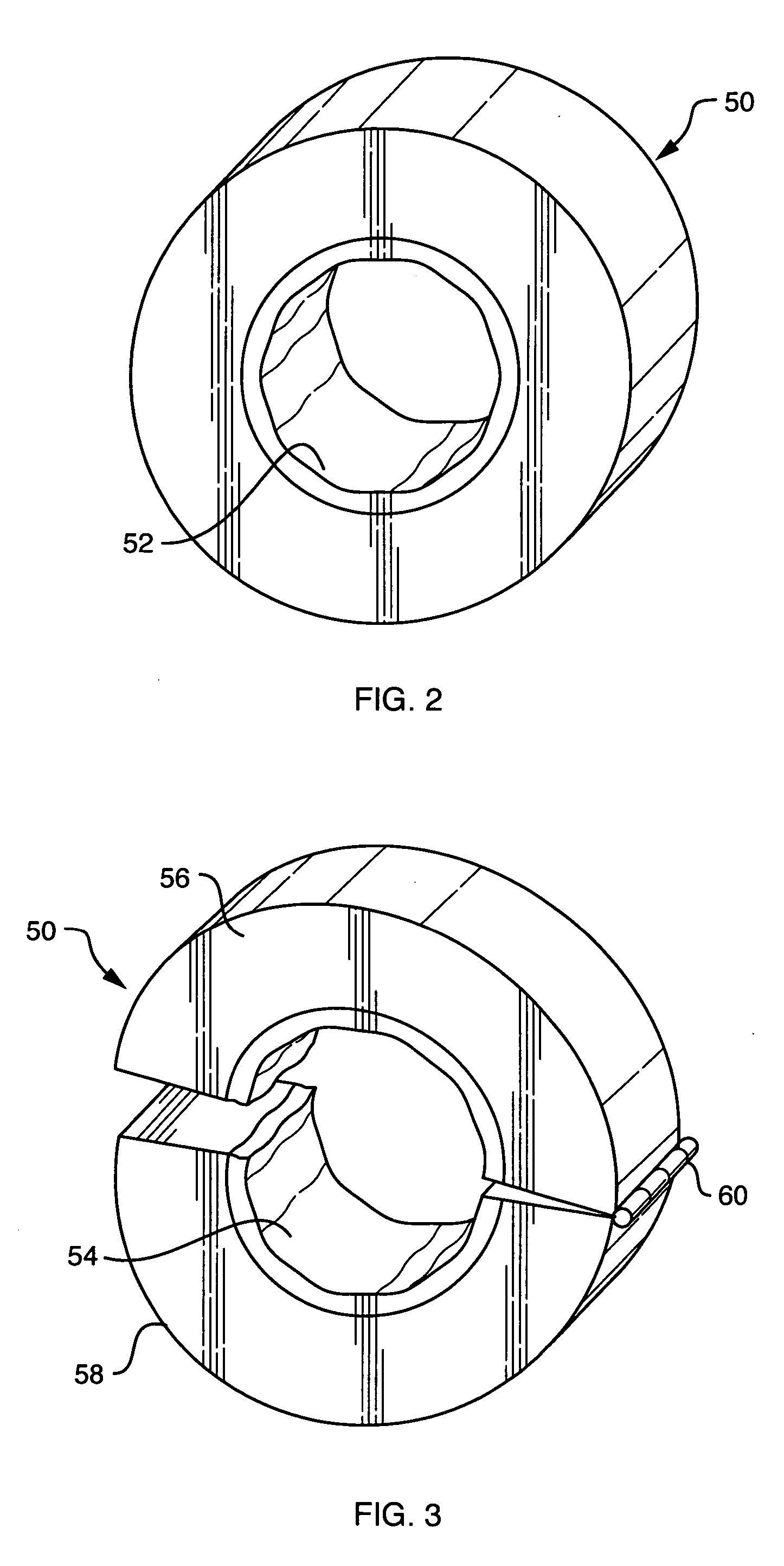
[0033] As illustrated in FIG. 3, the adjustable retainer 50 is a hinged annular ring or bushing fabricated of a selectable material. The hinged adjustable retainer 50 includes an interior structure 54 that may cover a portion or substantially all of the inside dimensions of the adjustable retainer 50. The hinged adjustable retainer 50 further includes a first piece 56, a second piece 58, and a hinge joint 60 hingedly connecting the two. As with the interior structure 52 of unitary adjustable retainer 50 of FIG. 2, the interior structure 54 is configured to enhance frictional contact between the adjustable retainer 50 and the outer surface of the strand 12. The interior structure may be configured with selectable frictional characteristics as described with respect the interior structure 52 of FIG. 2. The first piece 56 and the second piece 58 preferably including a latching mechanism or locking mechanism, such as a pressure fit tongue-and-groove arrangement for releasable clamping o...


PUM


Abstract

A modifiable jewelry piece including a strand and one or more adjustable retainers. The adjustable retainers include an interior structure configured to establish a frictional engagement with the outer surface of the strand. The jewelry piece wearer may select the location of the placement of the adjustable retainer anywhere along the length of the strand. The interior structure may be a solid or semi-solid having high surface tension or rough surface profile. The interior structure may alternatively be a mechanical capturing device. The jewelry piece also includes one or two end connectors having a slot and flange arrangement for easy passage of beads thereover only when desired. The flange and slot are arranged for alignment with threaded and flanged beads.

Description

BACKGROUND OF THE INVENTION [0001] 1. Field of the Invention [0002] The present invention relates to bracelets and necklaces. More particularly, the present invention relates to bracelets and necklaces arranged to enable a wearer to change beads and adjust the positioning of beads thereon. Still more particularly, the present invention relates to bracelets and necklaces including adjustable means for bead position retention. The present invention also includes an improved end connector arrangement to facilitate bead placement on bracelets and necklaces. [0003] 2. Description of the Prior Art [0004] Jewelry bracelets and necklaces of the type having two end connectors or clasps, allow the wearer to place the jewelry around the wrist or neck, secure it in position, and be reasonably assured that it will not pass over the hand or head. Such jewelry is generally formed as a strand, chain or band with the end connectors or clasps at opposing ends thereof. The end connectors may be joined...

Claims


Application Information

Patent Timeline
Patent Type & Authority Applications(United States)
IPC IPC(8): F01N3/10
CPCA44C5/0053A44C25/001A44C15/005A44C11/002
Inventor JULKOWSKI, JEFFSERGENT, TROY
Owner CHAMILIA
Why Eureka
Eureka Blog
Learn More