Neutral valve structure

a technology of neutral valves and valve bodies, applied in the direction of fluid couplings, couplings, mechanical equipment, etc., can solve the problems of enlargement, high production costs, and worsening and achieve the effect of preventing the deterioration of the transmission efficiency of the hst and low cos

Inactive Publication Date: 2006-11-23
KANZAKI KOKYUKOKI MFG
View PDF4 Cites 6 Cited by
  • Summary
  • Abstract
  • Description
  • Claims
  • Application Information

AI Technical Summary

Benefits of technology

[0018] With the configuration, it is possible to prevent the deterioration of the transmission efficiency of the HST in a state where the hydraulic pressure of the corresponding operation fluid line becomes high, while obtaining the neutral state of the HST without a strict operation.
[0051] Furthermore, since the positioning control of the valve body is performed by using the pressure difference between the closing-side pressure-receiving portion and the releasing-side pressure-receiving portion as a pilot pressure, the miniaturization of the neutral valve structure can be attained at low cost.

Problems solved by technology

However, the first configuration is not preferable in view of the transmission efficiency of the HST, since the operation oil is constantly leaked from the operation fluid line on the side at which the orifice is provided.
However, the transmission efficiency of the HST is worsened.
However, since the biasing member receives the hydraulic pressure of the corresponding operation fluid line as it is in the second configuration, a biasing member having a large spring load has to be used, and thereby there was a problem of causing enlargement and high production costs.

Method used


Image

  • Neutral valve structure
  • Neutral valve structure
  • Neutral valve structure

Examples


embodiment 1

[0071] Hereinafter, a first preferred embodiment of a neutral valve structure according to the present invention will be described referring to the accompanying drawings.

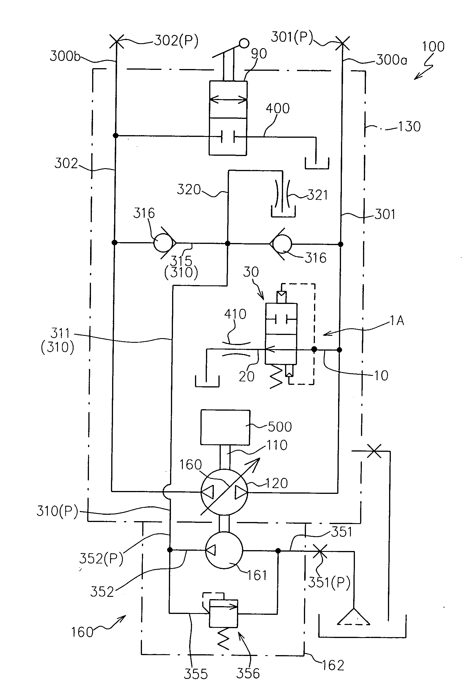
[0072]FIG. 1 shows a hydraulic circuit diagram of a hydraulic pump unit 100 to which a neutral valve structure 1A according to the present embodiment is applied.

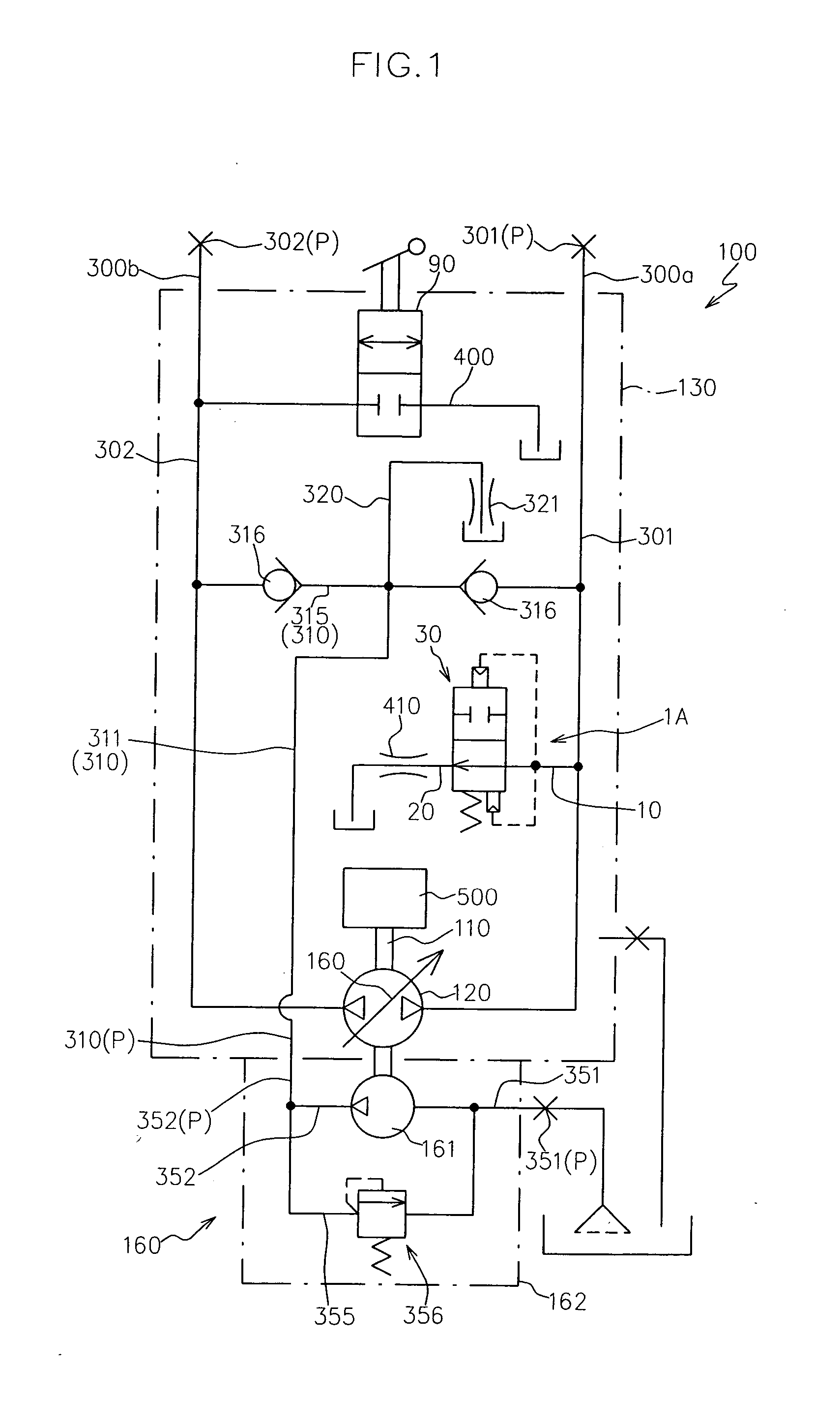
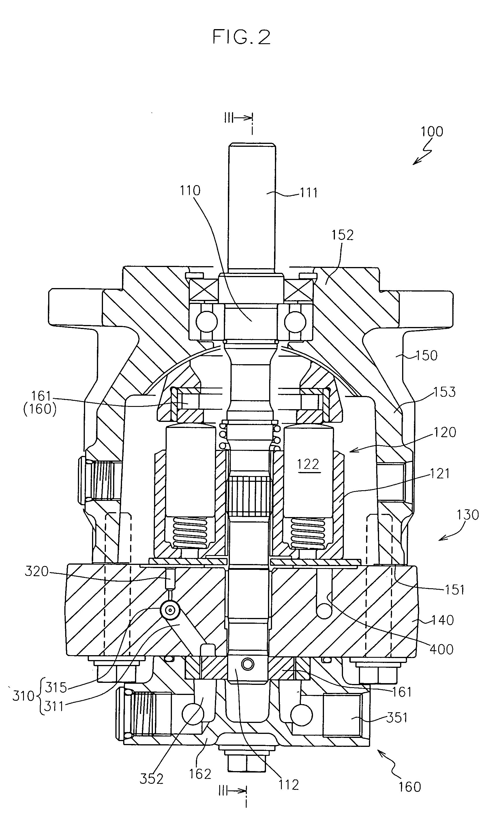
[0073]FIG. 2 shows a longitudinal sectional view of the hydraulic pump unit 100, and FIG. 3 shows a sectional view taken along line III-III in FIG. 2.

[0074] The hydraulic pump unit 100 is configured so as to be fluidly connected to a hydraulic motor unit (not shown) arranged away from the hydraulic pump unit with a space via a pair of first and second operation fluid lines 300a, 300b (see FIG. 1) so as to form an HST in cooperation with the hydraulic motor unit.

[0075] Specifically, as shown in FIGS. 1 to 3, the hydraulic pump unit 100 includes a pump shaft 110 operatively connected to a driving source 500, a hydraulic pump body 120 supported in a relativ...

embodiment 2

[0144] Hereinafter, a second embodiment of a neutral valve structure according to the present invention will be described referring to the accompanying drawings.

[0145]FIG. 5 shows a cross sectional view of a port block 140B in a hydraulic pump unit to which a neutral valve structure 1B according to the present embodiment is applied.

[0146] The same members as those of the embodiment 1 are designated by the same reference numerals, and the repeated description is omitted.

[0147] As shown in FIG. 5, the neutral valve structure 1B according to the present embodiment includes the neutral valve 30A acting on the second operation passage 302 instead of the switch valve 90 in the neutral valve structure 1A according to the embodiment 1.

[0148] That is, the neutral valve structure 1B includes the neutral valve 30A attached from the base-end-side opening of the installation passage 10 so as to act on the first operation passage 301, and the neutral valve 30A attached from the tip-end-side o...

embodiment 3

[0152] Hereinafter, a third embodiment of a neutral valve structure according to the present invention will be described referring to the accompanying drawings.

[0153] In the present embodiment, explanation will be made with taking an example where the neutral valve structure according to the present invention is applied to an HST in which the hydraulic pump unit and the hydraulic motor unit are integrated.

[0154]FIG. 6 shows a hydraulic circuit diagram of an HST 200 to which a neutral valve structure 1C according to the present embodiment is applied.

[0155] The same members as those of the embodiments 1, 2 are designated by the same reference numerals, and the repeated description is omitted.

[0156] As shown in FIG. 6, the HST 200 includes the pump shaft 110, the hydraulic pump body 120, a hydraulic motor body 220 fluidly connected to the hydraulic pump body 120 via the pair of first and second operation fluid lines 300a, 300b, a motor shaft 210 rotated and driven by the hydraulic ...


PUM


Abstract

There is provided a neutral valve structure applied to at least one of a pair of operation fluid lines in an HST, including: a valve body slidable in the axis line direction so as to take a closing position where the corresponding operation fluid line is liquid-tightly closed and a releasing position where the corresponding operation fluid line is released to a low-pressure area; and a biasing member for urging the valve body toward the releasing position on one side of the axis line direction. The valve body includes: a closing-side pressure-receiving portion for receiving the hydraulic pressure of the corresponding operation fluid line so as to press the valve body toward the closing position on the other side of the axis line direction against the urging force of the biasing member; and a releasing-side pressure-receiving portion for receiving the hydraulic pressure of the corresponding operation fluid line so as to press the valve body toward the releasing position on one side of the axis line direction along with the biasing member. The closing-side pressure-receiving portion has a receiving pressure area larger than that of the releasing-side pressure-receiving portion.

Description

BACKGROUND OF THE INVENTION [0001] 1. Field of the Invention [0002] The invention relates to a neutral valve structure applied to an HST or an axial piston device forming the HST. [0003] 2. Related Art [0004] In a hydrostatic transmission (HST) including a hydraulic pump body and a hydraulic motor body that are fluidly connected to each other by a pair of operation fluid lines, and configured to non-stepwisely change the rotational speed that is inputted into the hydraulic pump body and output the same through a motor shaft supporting the hydraulic motor body by varying oil supply / suction amount of at least one of the hydraulic pump body and the hydraulic motor body based on the operation of an output adjusting member, two following configurations have been conventionally proposed in order to obtain a neutral state (a state where the output of the hydraulic motor unit is zero), without locating the output adjusting member at a neutral point strictly. [0005] In a first configuration,...

Claims


Application Information

Patent Timeline
Patent Type & Authority Applications(United States)
IPC IPC(8): F16D31/02F16H61/40
CPCF16D31/00
Inventor SAKIKAWA, SHIGENORI
Owner KANZAKI KOKYUKOKI MFG
Why Eureka
Try Eureka