Method and apparatus for providing for high EGR gaseous-fuelled direct injection internal combustion engine

Inactive Publication Date: 2006-11-23
WESTPORT FUEL SYST CANADA INC +1
View PDF9 Cites 9 Cited by
  • Summary
  • Abstract
  • Description
  • Claims
  • Application Information

AI Technical Summary

Benefits of technology

[0008] The present method and apparatus secure high EGR rates while managing emissions that tend to result from such high EGR levels. The emissions at high

Problems solved by technology

For all their advantages, diesel-fuelled engines have a significant disadvantage.
When burned substantially in a diffusion combustion mode, diesel fuel generates high levels of some pollutants.
Pollutants such as oxides of nitrogen (NOx) and particulate matter (

Method used


Image

  • Method and apparatus for providing for high EGR gaseous-fuelled direct injection internal combustion engine
  • Method and apparatus for providing for high EGR gaseous-fuelled direct injection internal combustion engine
  • Method and apparatus for providing for high EGR gaseous-fuelled direct injection internal combustion engine

Examples


Example

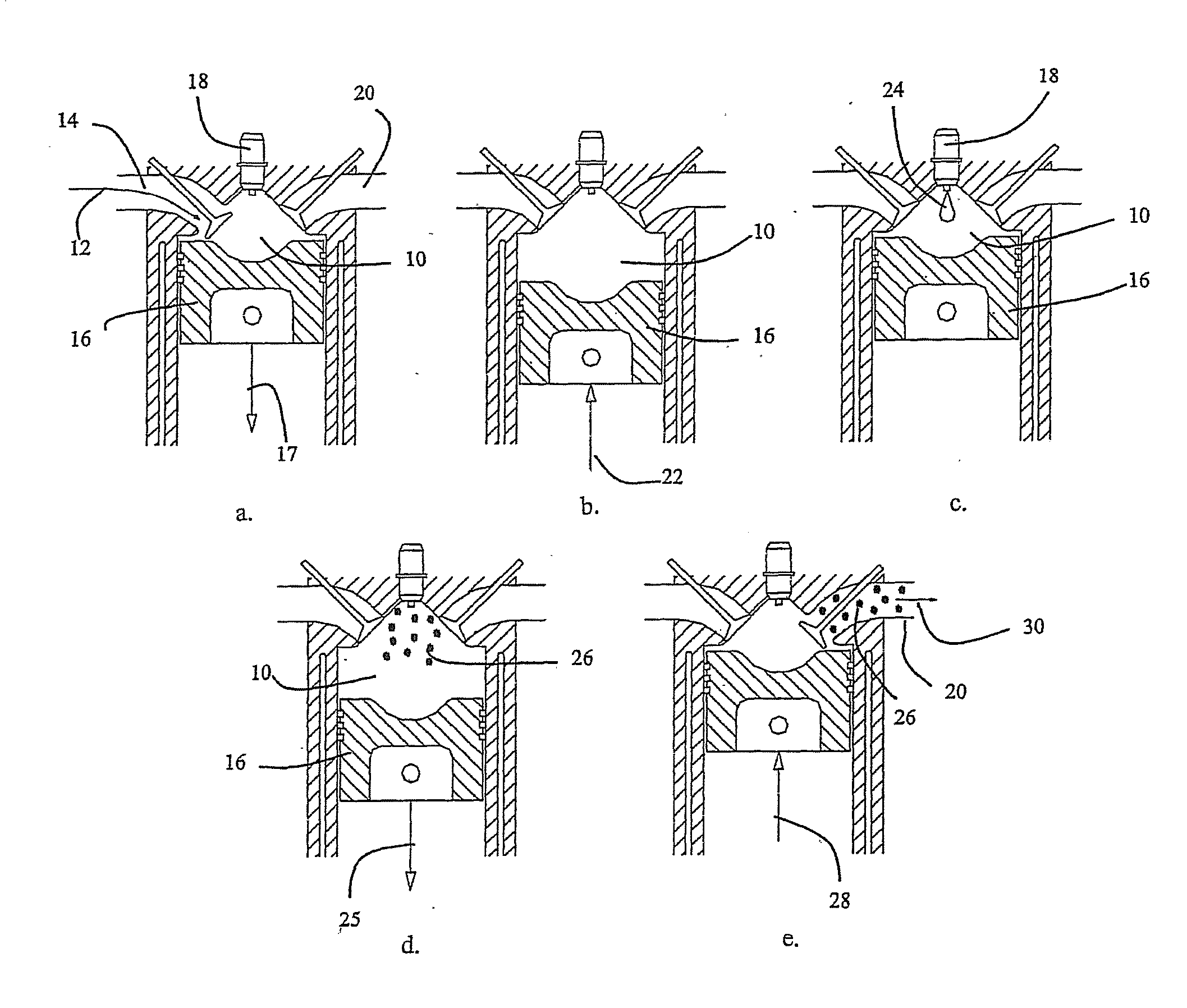
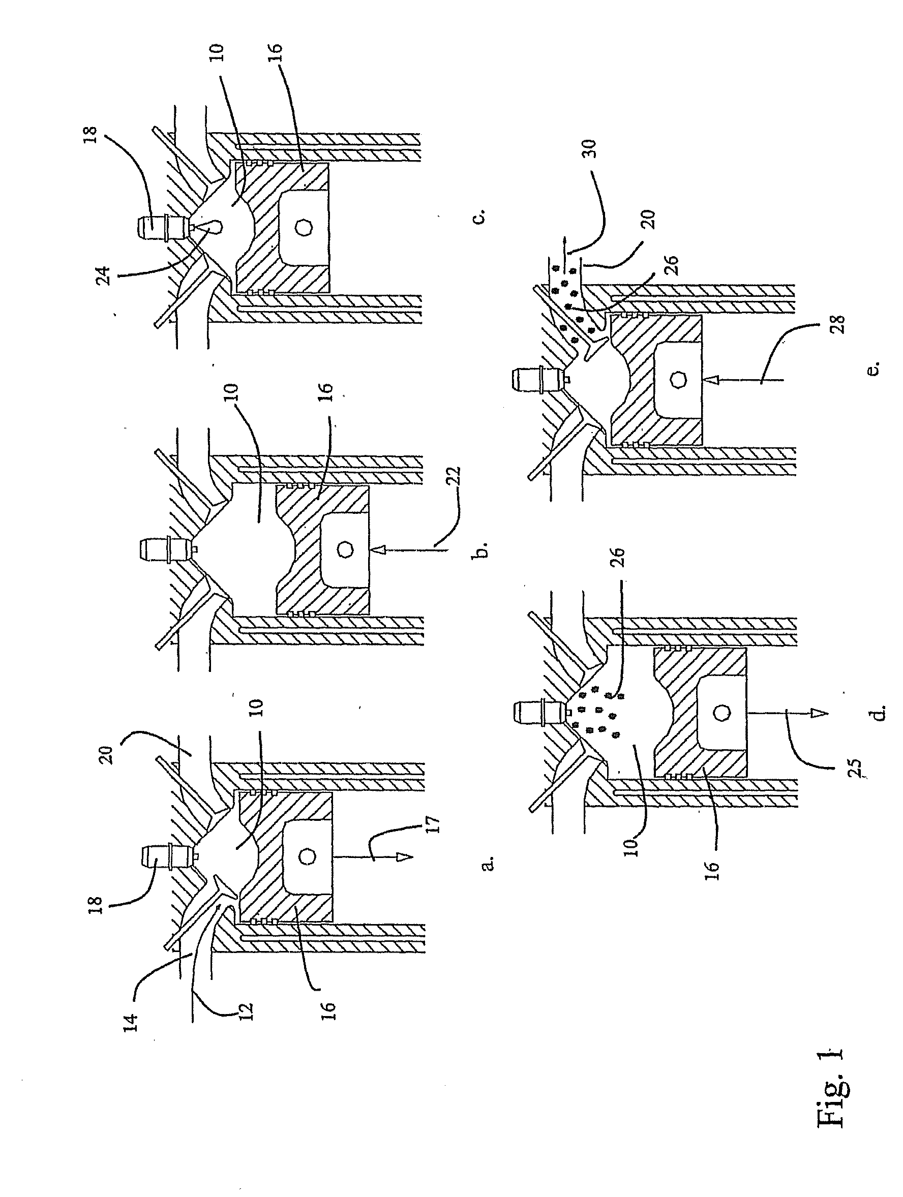
[0021] The present method and apparatus secure high EGR levels in a gaseous-fuelled direct injection engine by adjusting pilot timing in response to target EGR levels.

[0022] Referring to FIG. 1, a cross-section providing the stages in a cycle of a typical gaseous-fuelled direct injection engine is shown. FIG. 1a provides an intake charge introduced into combustion chamber 10 through intake line 14 in direction 12. The intake charge can include any combination of fresh air, EGR, water and gaseous fuel. At the same time, piston 16 is, during the intake stroke, moving in direction 17 away from injector 18, which is disposed in a fire deck and in fluid communication with combustion chamber 10. Also shown is exhaust line 20. FIG. 1b demonstrates piston 16 moving in direction 22 compressing the charge within the combustion chamber during the compression stroke of the engine. Referring to FIG. 1c, pilot fuel 24 can be introduced into combustion chamber 10 when the piston is at or near top...


PUM


Abstract

A method and apparatus adjust pilot fuel injection timing in relation to a main fuel injection timing into a piston cylinder of an operating gaseous-fuelled direct injection internal combustion engine using high levels of EGR. A set of engine parameters are monitored which determine engine load and engine speed and an indicator of EGR concentration within the intake charge. Pilot fuel timing relative to main fuel injection timing is then adjusted according to the engine parameters. High levels of EGR are shown to be tolerated with relatively limited penalties in relation to other emissions typically found with high EGR by reducing the relative injection timing the pilot fuel as compared to main fuel injection timing.

Description

CROSS-REFERENCE TO RELATED APPLICATION(S) [0001] This application is a continuation of International Application No. PCT / CA2004 / 001736, having an international filing date of Sep. 23, 2004, entitled “Method And Apparatus For Providing For High EGR Gaseous-Fuelled Direct Injection Internal Combustion Engine”. International Application No. PCT / CA2004 / 001736 claimed priority benefits, in turn, from Canadian Patent Application No. 2,442,336 filed Sep. 30, 2003. International Application No. PCT / CA2004 / 001736 is hereby incorporated by reference herein in its entirety.FIELD OF THE INVENTION [0002] This invention relates to a method and apparatus for controlling emissions and engine performance to provide for high levels of exhaust gas recirculation (EGR; the recirculated exhaust stream is also referred to herein as EGR) in a gaseous-fuelled direct injection engine. BACKGROUND OF THE INVENTION [0003] For all their advantages, diesel-fuelled engines have a significant disadvantage. When bur...

Claims


Application Information

Patent Timeline
IPC IPC(8): F02B3/00F02M43/00F02M21/02F02M25/07F02B23/06F02B77/08F02D21/08
CPCF02B23/0675Y02T10/36F02B77/08F02B2275/14F02D13/0265F02D19/10F02D41/0027F02D41/0072F02D41/144F02M25/0707F02M25/0709F02M25/0713F02M25/0727F02M25/0752F02M25/0755Y02T10/125Y02T10/123Y02T10/47F02D19/061F02M25/028F02B29/0406F02M26/01F02M26/05F02M26/06F02M26/10F02M26/23F02M26/46Y02T10/12Y02T10/30Y02T10/40
Inventor MUNSHI, SANDEEPMCTAGGART-COWAN, GORDON P.BUSHE, W. KENDALROGAK, STEVEN N.
Owner WESTPORT FUEL SYST CANADA INC
Why Eureka
Try Eureka