Control apparatus for internal combustion engine

a control apparatus and internal combustion engine technology, applied in the direction of electric control, combustion engines, machines/engines, etc., can solve the problems that the internal combustion engine and/or the combustion noise cannot meet the requirements, and achieve the effect of preventing the deterioration of the ignitability of the pre-spray by the ignition device, reducing the amount of smoke generated, and reducing the quantity of oxygen available for combustion of the second injected fuel

Inactive Publication Date: 2017-10-05
TOYOTA JIDOSHA KK
View PDF32 Cites 14 Cited by
  • Summary
  • Abstract
  • Description
  • Claims
  • Application Information

AI Technical Summary

Benefits of technology

[0019]As the second injection ratio is made lower when the EGR rate is high than when the EGR rate is low, the smaller the quantity of oxygen in the combustion chamber is, the smaller the quantity of fuel existing in the region in which fuel spray is formed at the time when the second injection is performed can be made. Therefore, deficiency in the quantity of oxygen available for combustion of the second injected fuel can be prevented. Consequently, the amount of smoke generated can be reduced. Furthermore, as the first injection ratio is made higher when the EGR rate is high than when the EGR rate is low, the larger the quantity of inert gas in the combustion chamber is, the larger the quantity of fuel ignited by the ignition device can be made. Therefore, deterioration in the ignitability in ignition of the pre-spray by the ignition device can be prevented. Consequently, the stability of diesel combustion can be improved.
[0020]The higher the EGR rate is, the larger the quantity of inert gas in the combustion chamber is, and therefore the less likely the flame generated by ignition of the pre-spray by the ignition device is to propagate extensively. Therefore, the higher the EGR rate is, the higher the unburned residue rate of the first injected fuel (i.e. the proportion of the first injected fuel that is not burned by propagation of flame generated by ignition of the pre-spray by the ignition device but remains unburned) is. Therefore, if the first injection ratio is made higher when the EGR rate is high than when the EGR rate is low, while the quantity of fuel ignited by the ignition device increases as described above, the quantity of the first injected fuel that remains unburned increases more than the quantity of the first injected fuel that is burned by propagation of flame generated by the ignition. The unburned residue of the first injected fuel is diffused more extensively than the region in the combustion chamber in which spray of the second injected fuel is formed at the second injection time. Consequently, even when the EGR rate is high, a sufficient quantity of oxygen needed to burn the unburned residue of the first injected fuel by self-ignition or diffusion combustion can be provided. Therefore, if the first injection ratio is increased when the EGR rate is high, the amount of smoke generated is unlikely to increase. The unburned residue of the first injected fuel contributes to the promotion of self-ignition of fuel after the start of the second injection. Therefore, as the quantity of the unburned residue of the first injected fuel is increased by increasing the first injection ratio for higher EGR rates, self-ignition of fuel after the start of the second injection is promoted. This also contributes to the improvement in the stability of diesel combustion.
[0021]As the first injection ratio is made lower when the EGR rate is low than when the EGR rate is high, the smaller the quantity of inert gas in the combustion chamber is, the smaller the quantity of the first injected fuel existing in the combustion chamber can be made. Consequently, the quantity of fuel burned by propagation of flame caused by ignition by the ignition device under the circumstances where the quantity of inert gas in the combustion chamber is small can be made small. In other words, the quantity of oxygen consumed in combustion of the first injected fuel before the second injection is performed can be made small. Therefore, deficiency in the quantity of oxygen available for combustion of the second injected fuel can be prevented when the second injection is performed. In consequence, the amount of smoke generated can be reduced.
[0022]The control apparatus for an internal combustion engine according to the present invention may further comprise a first EGR rate control unit that controls the EGR rate in the intake air based on the engine load of the internal combustion engine and a first determination unit that determines a base first injected fuel quantity and a base second injected fuel quantity, based on the engine load of the internal combustion engine. The base first injected fuel quantity is a base value of the first injected fuel quantity, and the base second injected fuel quantity is a base value of the second injected fuel quantity. When the EGR rate in the intake air is changed by the first EGR rate control unit during transient operation for changing the engine load of the internal combustion engine to a target engine load, there is a response delay in changing the EGR rate. Therefore, during the response delay period in changing the EGR rate during transient operation in which the EGR rate is decreased, the actual EGR rate is higher than a target EGR rate corresponding to the target engine load. On the other hand, during the response delay period in changing the EGR rate during transient operation in which the EGR rate is increased, the actual EGR rate is lower than the target EGR rate corresponding to the target engine load corresponding to the engine load.
[0023]In view of the above circumstances, in the apparatus according to the present invention, when the EGR rate in the intake air is decreased by the first EGR rate control unit during transient operation by which the engine load of the internal combustion engine is changed to the target engine load, the combustion control unit may perform the said first fuel injection control by making the first injected fuel quantity larger than the base first injected fuel quantity corresponding to the target engine load and making the second injected fuel quantity smaller than the base second injected fuel quantity corresponding to the target engine load, during at least a part of the period during which the actual EGR rate in the intake air is higher than the target EGR rate corresponding to the target engine load. with this control, the first injection ratio is made higher and the second injection ratio is made lower when the actual EGR rate in the intake air is higher than the target EGR rate corresponding to the target engine load during transient operation of the internal combustion engine than when the actual EGR rate in the intake air is equal to the target EGR rate. Therefore, the amount of smoke generated can be reduced, and the stability of diesel combustion can be improved during transient operation.
[0024]In the apparatus according to the present invention, when the EGR rate in the intake air is increased by the first EGR rate control unit during transient operation by which the engine load of the internal combustion engine is changed to the target engine load, the combustion control unit may perform said first fuel injection control by making the first injected fuel quantity smaller than the base first injected fuel quantity corresponding to the target engine load and making the second injected fuel quantity larger than the base second injected fuel quantity corresponding to the target engine load, during at least a part of the period during which the actual EGR rate in the intake air is lower than the target EGR rate corresponding to said target engine load. With this control, the first injection ratio is made lower and the second injection ratio is made higher when the actual EGR rate in the intake air is lower than the target EGR rate corresponding to the target engine load during transient operation of the internal combustion engine than when the actual EGR rate in the intake air is equal to the target EGR rate. Therefore, the amount of smoke generated during the transient operation can be reduced.

Problems solved by technology

If the EGR rate deviates from a range suitable for the operation state of the internal combustion engine due to this response delay in the EGR rate, there is a possibility that the torque of the internal combustion engine and / or the combustion noise cannot meet the requirements.

Method used


Image

  • Control apparatus for internal combustion engine
  • Control apparatus for internal combustion engine
  • Control apparatus for internal combustion engine

Examples


example 1

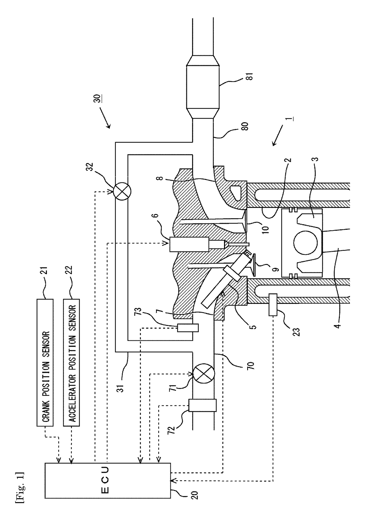
[0068]FIG. 1 is a diagram showing the general configuration of the air-intake and exhaust systems of an internal combustion engine to which the present invention is applied. The internal combustion engine 1 shown in FIG. 1 is a four-stroke-cycle, spark-ignition internal combustion engine (gasoline engine) having a plurality of cylinders. FIG. 1 shows only one of the plurality of cylinders.

[0069]In each cylinder 2 of the internal combustion engine 1, a piston 3 is provided in a slidable manner. The piston 3 is linked with an output shaft (crankshaft), which is not shown in the drawings, by a connecting rod 4. The interior of the cylinder 2 is in communication with intake ports 7 and exhaust ports 8. An end of the intake port 7 opening into the cylinder 2 is opened / closed by an intake valve 9. An end of the exhaust port 8 opening into the cylinder 2 is opened / closed by an exhaust valve 10. The intake valve 9 and the exhaust valve 10 are driven to be opened / closed respectively by an in...

example 2

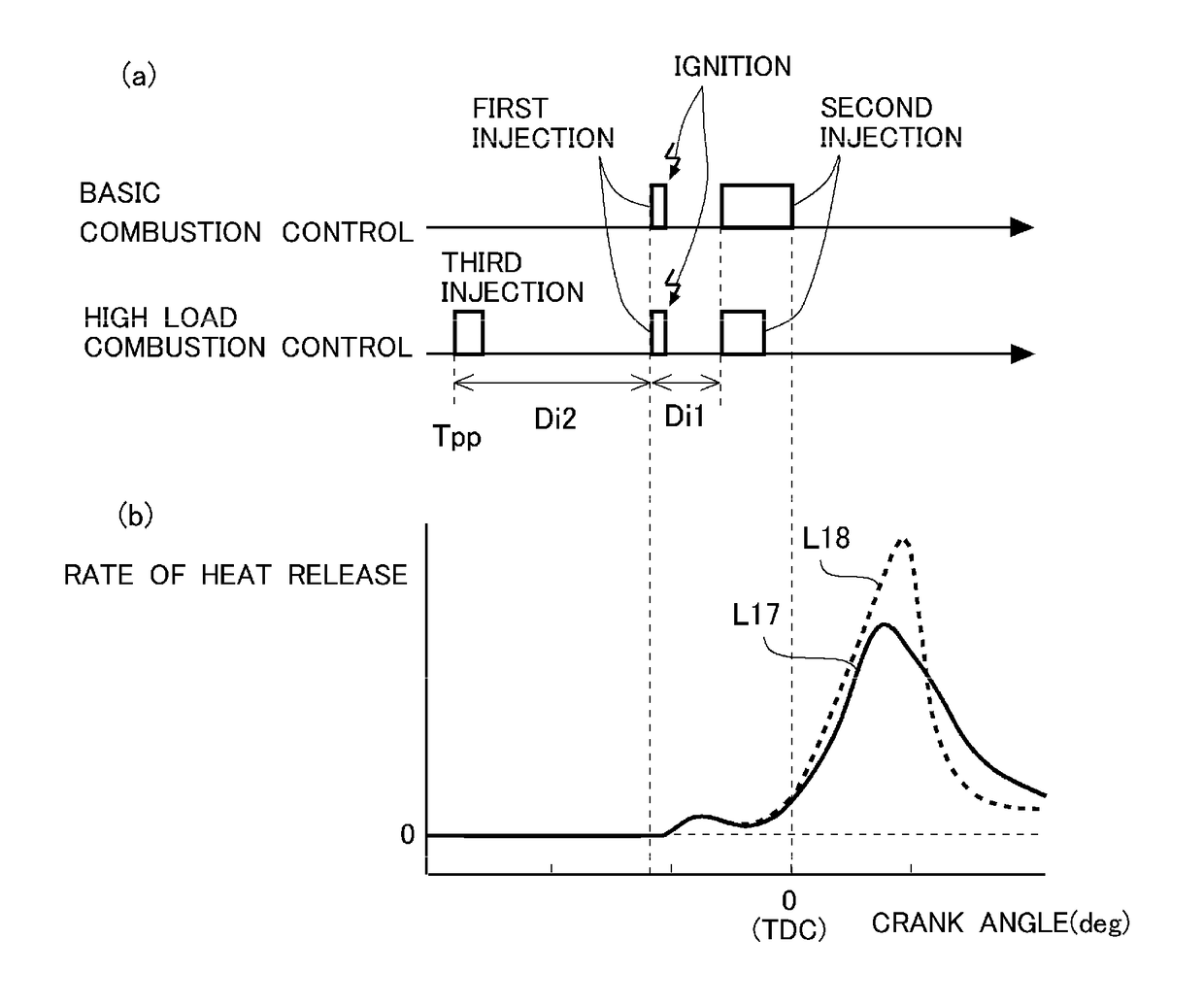
[0179]In this example, operation ranges equivalent to the low load range R3, the middle load range R4, and the high load range R5 shown in FIG. 16 will be referred to as low load range R3, first middle load range R4, and second middle load range R5. In this example also, the basic combustion control and the transient operation control same as those in example 1 are performed in the low load range R3, the first middle load range R4, and the second middle load range R5. In this example, the operation range in which the engine load is higher than the second middle load range will be referred to as high load range, in which high load combustion control is performed. In the following, the high load combustion control according to this example will be described.

[0180]

[0181]In the internal combustion engine 1, when the engine load increases, it is necessary to increase the quantity of fuel injected into the combustion chamber. However, as described above, if the second injected fuel quanti...

example 3

[0234]In example 3, the base combustion control same as that in example 1 is performed. In this example, when the engine temperature of the internal combustion engine 1 is low, the supply of EGR gas into the intake air by the EGR apparatus 30 is suspended in order to raise the temperature of the internal combustion engine 1 and the exhaust gas quickly.

[0235]

[0236]In the following, a control flow of the EGR control according to this example will be described with reference to FIG. 23. FIG. 23 is a flow chart of the control flow of the EGR control according to this example. Steps S101 through S104 in this flow are the same as those in the flow shown in FIG. 12, and the processing in these steps will not be described. This control flow is stored in the ECU 20 in advance and carried out repeatedly at predetermined intervals by executing a control program stored in the ECU 20 while the internal combustion engine 1 is operating.

[0237]In this flow, firstly in step S601, it is determined wh...


PUM


Abstract

An object of the invention is to reduce the amount of smoke generated and to improve the stability of diesel combustion in cases where an EGR apparatus is used in an internal combustion engine that performs diesel combustion using fuel having a relatively high self-ignition temperature. A control apparatus performs first injection at a first injection time during the compression stroke, causes spray guide combustion to occur, and starts to perform second injection at such a second injection time that causes combustion of injected fuel to be started by flame generated by the spray guide combustion, thereby causing self-ignition and diffusion combustion of fuel to occur. The apparatus changes the ratio of the first injected fuel quantity to the total fuel injection quantity and the ratio of the second injected fuel quantity to the total fuel injection quantity for the same total fuel injection quantity in one combustion cycle, based on the EGR rate in the intake air.

Description

TECHNICAL FIELD[0001]The present invention relates to a control apparatus for an internal combustion engine.BACKGROUND ART[0002]What is called diesel combustion, in which fuel is directly injected into compressed air in the combustion chamber, self-ignites, and is burned by diffusion combustion, has a higher thermal efficiency as compared to combustion by spark ignition. In recent years, in order to enjoy this advantage of diesel combustion also in gasoline engines, technology for causing gasoline to self-ignite and burn by diffusion combustion has been developed.[0003]PTL 1 discloses a technology enabling diesel combustion using as fuel natural gas or the like having a relatively high self-ignition temperature. According to PTL 1 disclosing this technology, fuel injection is performed in a predetermined spark-ignition region in the combustion chamber in an early or middle stage of the compression stroke to form air-fuel mixture that can be spark-ignited. Then, the air-fuel mixture ...

Claims


Application Information

Patent Timeline
Patent Type & Authority Applications(United States)
IPC IPC(8): F02B23/10F02D41/30F02D41/40F02D41/00
CPCF02B23/101F02D41/403F02D41/3023F02D41/0057F02B2023/103F02D41/10F02D41/12F02D41/3011F02D41/3818F02D41/40F02D2041/389F02D2200/021F02D2200/602F02D2250/38Y02T10/12Y02T10/40
Inventor OCHI, YUTAKASHIWAGURA, TOSHIMI
Owner TOYOTA JIDOSHA KK
Why Eureka
Try Eureka