Direct injection diesel engine

a diesel engine and direct injection technology, applied in the direction of combustion engines, electric control, pistons, etc., can solve the problems that the effect of emission control and the effect of fuel consumption reduction cannot be expected, and achieve the effect of reducing smok

Active Publication Date: 2005-06-02
KOMATSU LTD
View PDF5 Cites 20 Cited by
  • Summary
  • Abstract
  • Description
  • Claims
  • Application Information

AI Technical Summary

Benefits of technology

[0009] A main object of the present invention is to provide a direct injection diesel engine capable of suppressing NOx generation, reducing smoke, and also reducing fuel consumption rate.

Problems solved by technology

Therefore, in the document above, when a fuel injection period is largely changed, it is impossible to accurately distribute a half of the fuel to the troidal and a remaining half of the fuel to the open chamber, so that the effect in emission control and the effect in reduction of fuel consumption rate can hardly be expected.

Method used


Image

  • Direct injection diesel engine
  • Direct injection diesel engine
  • Direct injection diesel engine

Examples


first embodiment

[0042] the present invention is described below with reference to the related drawings.

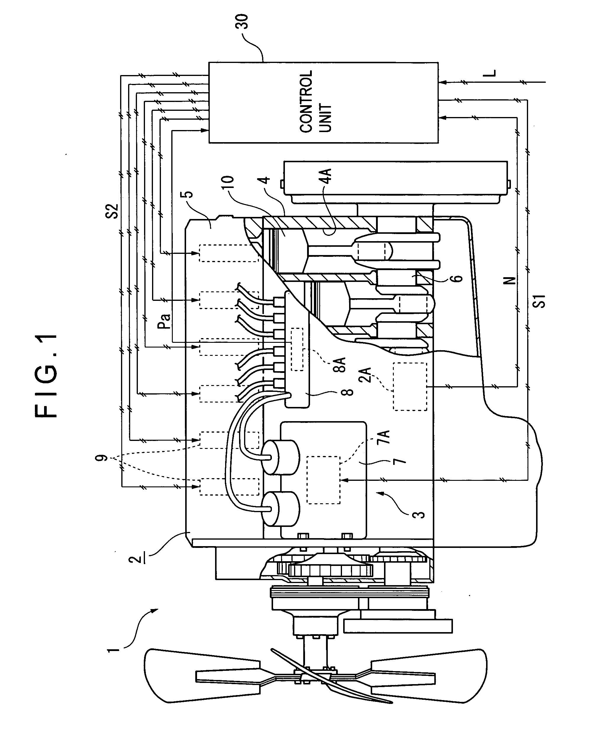
[0043]FIG. 1 is a partial cross-sectional view showing a direct injection diesel engine 1 according to a first embodiment of the present invention. In this FIG. 1, the diesel engine 1 is used for driving various types of construction machines such as a dump truck, a bulldozer, a hydraulic shovel, and a wheel loader, or a large size generator, and comprises an engine body 2 and a fuel injector 3 for feeding fuel to the engine body 2.

[0044] The engine body 2 comprises a cylinder block with a plurality of cylinders 4A formed therein, a cylinder head 5 bolted or otherwise fixed in an upper section of the cylinder block 4, a plurality of pistons 10 reciprocally moving within the plurality of cylinders 4A under a pressure by combustion gas burnt in each of the cylinders 4A, and a crank shaft 6 for converting reciprocal movement of the piston 10 to rotational movement.

[0045] The fuel injector 3 compris...

second embodiment

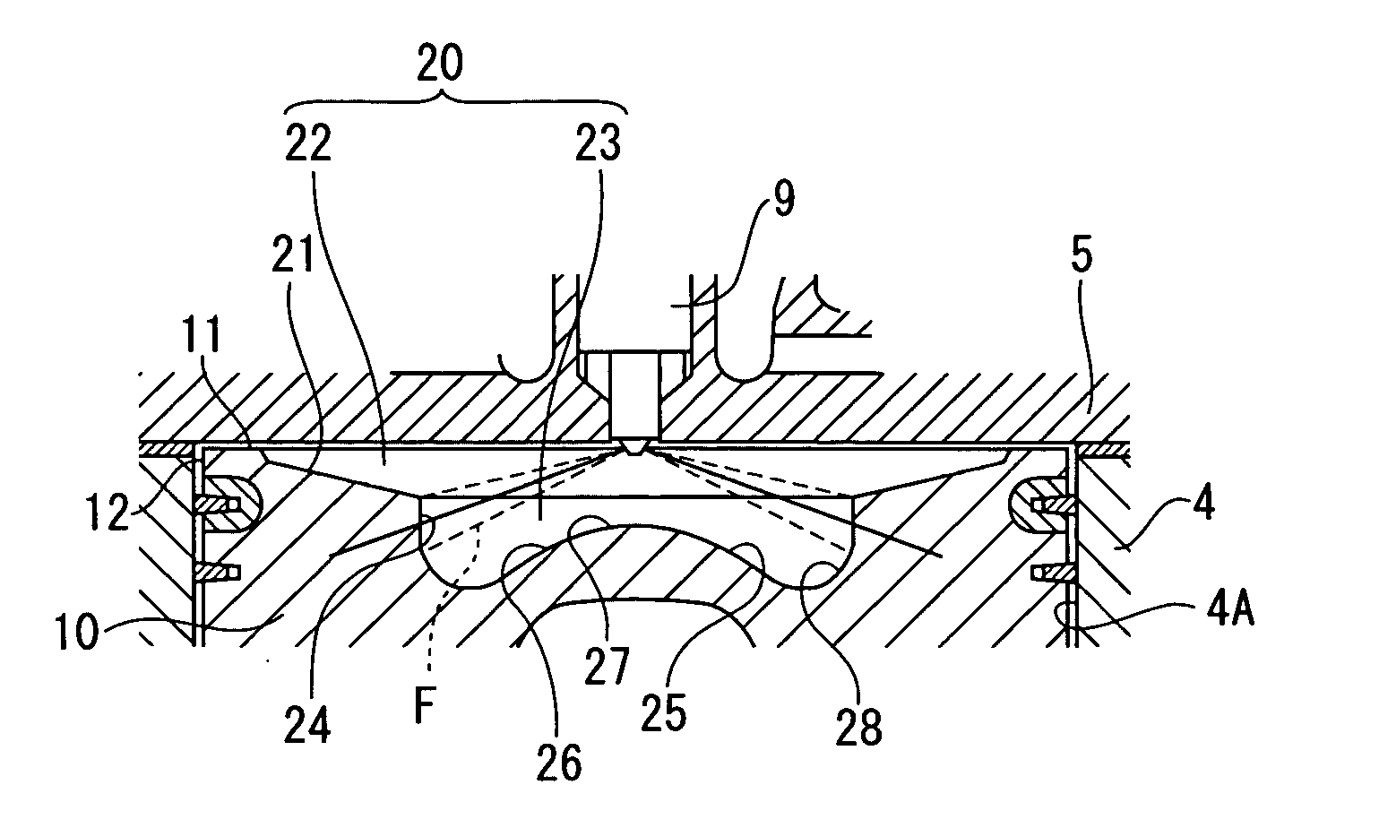
[0066]FIG. 9 is a side cross-sectional view showing the shape of the combustion chamber 20 according to the present invention.

[0067] Provided on the top face 11 of the piston 10 is the first volume 22 having a bottom surface substantially parallel to the top face 11 and having a recessed section with a prespecified depth, and further the second volume 23 having a circular shape when viewed from the top and also having a recessed cross section is provided at a center of the bottom surface. The inner peripheral wall section 24 of the second volume 23 inclines and purses toward the bottom. The conical section 26 is provided on a bottom surface of the second volume 23 like in the first embodiment.

third embodiment

[0068]FIG. 10 is a side cross-sectional view showing the shape of the combustion chamber 20 according to the present invention.

[0069] This embodiment is different from the first embodiment in the point that the inner peripheral wall section 24 of the second volume 23 inclines and widens toward the bottom. Other portions have the same shape as those in the first embodiment.


PUM


Abstract

A combustion chamber (20) opening toward a cylinder head (5) is provided on a top surface (11) of a piston (10), and this combustion chamber (20) comprises a first volume (22) having an inclined surface (20) and a second volume (23) further recessed from the first volume (22) toward a pin boss (13). Fuel spray F from a fuel injection nozzle (9) is injected toward an inner peripheral wall section (24) of the second volume (23) in a former stage of fuel injection and toward the inclined surface (21) of the first volume (22) in a later stage of fuel injection, and the percentage of the fuel injection period in the former stage against the total fuel injection period is set to the range from 40% to 70%.

Description

BACKGROUND OF THE INVENTION [0001] 1. Field of the Invention [0002] The present invention relates to direct injection diesel engines which inject fuel from a fuel injection nozzle provided on a cylinder head toward a combustion chamber provided on a piston top face section. [0003] 2. Description of Related Art [0004] Various propositions have been made from the view points of, for instance, reduction of NOx, reduction of smoke, and reduction of fuel consumption rate in relation to the shape of a combustion chamber provided on a piston top face section of a direct injection diesel engine as well as to the type of fuel injection (Refer to, for instance, Japanese Utility Model Laid-Open Publication No. SHO 58-183933). [0005] According to the utility model described in the aforesaid document, the combustion chamber comprises a troidal in a lower section of the combustion chamber and an open chamber section in an upper section of the combustion chamber, and by vertical movement of the pi...

Claims


Application Information

Patent Timeline
Patent Type & Authority Applications(United States)
IPC IPC(8): F02B3/00F02B3/06F02B3/08F02B15/00F02B23/06F02B23/08F02D41/40F02F3/26
CPCF02B3/06F02B23/0651F02B23/0669F02B23/0672Y02T10/123F02B23/0696F02B2275/14F02F3/26Y02T10/125F02B23/0693Y02T10/12
Inventor ONO, YUTAKAIIJIMA, TADASHITAKAHASHI, MASAKI
Owner KOMATSU LTD
Why Eureka
Try Eureka