
Controllable EGR system using integrated dual-channel EGR cooler

An EGR cooler and dual-channel technology, applied in the field of EGR systems, can solve the problems of limited EGR temperature adjustment range, no vortex pre-throttling function, and inability to realize EGR rate, etc. good effect

Active Publication Date: 2019-11-26
DONGFENG COMML VEHICLE CO LTD
View PDF1 Cites 8 Cited by
  • Summary
  • Abstract
  • Description
  • Claims
  • Application Information

AI Technical Summary

Problems solved by technology

[0004] First of all, this design can only realize cold EGR or hot EGR, and cannot use cold and hot EGR at the same time, resulting in limited adjustment range of EGR temperature;
[0005] Secondly, this design does not have a throttle function before the vortex, and cannot adjust the EGR driving pressure difference, so that a higher EGR rate cannot be achieved

Method used


Image

  • Controllable EGR system using integrated dual-channel EGR cooler
  • Controllable EGR system using integrated dual-channel EGR cooler
  • Controllable EGR system using integrated dual-channel EGR cooler

Examples


Embodiment 1

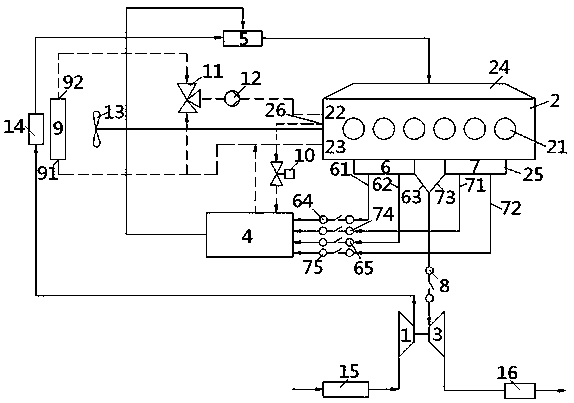
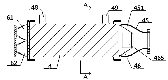
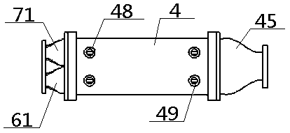
[0055] see Figure 1 to Figure 7 , a controllable EGR system using an integrated dual-channel EGR cooler, including a compressor 1, an engine 2, a turbine 3, an integrated cooler 4 and a mixer 5, and the compressor 1 is connected to the engine 2 through an intake manifold 24 The other end of the engine 2 is connected to the turbine 3 through the exhaust manifold 25; the inside of the integrated cooler 4 is provided with a cold one passage 41, a cold two passage 42, a hot one passage 43 and The second heat channel 44, the exhaust manifold 25 includes a first exhaust manifold 6 and a second exhaust manifold 7, and the first exhaust manifold 6 passes through the first A air passage 61 and the first B air passage respectively. Air channel 62, first third air channel 63 are connected with cold one channel 41, hot one channel 43, the intake end of turbine 3, and described second exhaust manifold 7 passes through second first air channel 71, the first third air channel respectively. ...

Embodiment 2

[0057] Basic content is the same as embodiment 1, the difference is:

[0058] The integrated cooler 4 includes an air outlet cover 45 and an air outlet chamber 451 provided inside, and a first check valve 46 and a second check valve 47 are arranged inside the air outlet chamber 451; 1. The gas outlets of the first hot channel 43 communicate with the air outlet chamber 451 of the device through the first one-way valve 46, and the gas outlets of the second cold channel 42 and the second hot channel 44 communicate with the air outlet chamber 451 of the device through the second one-way valve 47. connected. The structures of the No. 1 one-way valve 46 and the No. 2 one-way valve 47 are consistent, and both include a valve housing 461 and a valve inner chamber 462 provided therein. Both sides of the valve housing 461 are provided with a left valve port 463 and a right valve port. Valve port 464, left valve port 463, right valve port 464 are respectively provided with corresponding...


PUM


Abstract

The invention relates to a controllable EGR system using an integrated dual-channel EGR cooler. The system involves the integrated cooler and a double-channel structure formed by two exhaust manifolds, wherein the integrated cooler comprises two cold channels and two heat channels which are independent from one another, each exhaust manifold is connected with air inlet ends of one cold channel, one heat channel and a turbine through three air channels, the air outlet ends of the cold channels and the air outlet ends of the heat channels are connected with the air inlet end of a device air outlet cavity arranged in the integrated cooler, and the air outlet end of the device air outlet cavity and the air outlet end of an air compressor are connected with an engine after sequentially througha mixer and an air inlet manifold. According to the system, the EGR temperature and the EGR rate can be adjusted through a cold EGR and heat EGR combined mode, so that the adjusting capacity is high,and the EGR can be driven by utilizing exhaust pulse energy, so that the EGR rate and the driving capacity are improved.

Description

technical field [0001] The invention relates to an EGR system, which belongs to the technical field of engine exhaust gas recirculation, in particular to a controllable EGR system using an integrated dual-channel EGR cooler, which is specifically suitable for increasing the EGR rate and the adjustment range of the EGR temperature. Background technique [0002] EGR is the exhaust gas recirculation system, which refers to introducing part of the exhaust gas of the engine into the cylinder to reduce the combustion temperature in the cylinder, thereby reducing NOx emissions. EGR is divided into cold EGR and hot EGR. Cold EGR uses a cooler to cool part of the exhaust gas and then introduces it into the cylinder. Hot EGR means that the exhaust gas directly enters the cylinder without passing through the cooler. The temperature of cold EGR is lower than that of hot EGR. Realize lower in-cylinder combustion temperature and further reduce NOx emissions. [0003] The application publ...

Claims


Application Information

Patent Timeline
Patent Type & Authority Applications(China)
IPC IPC(8): F02M26/32F02M26/30F02M26/33F02M26/16F02M26/05F02M26/38F02B29/04
CPCF02B29/0437F02B29/0493F02M26/05F02M26/16F02M26/30F02M26/32F02M26/33F02M26/38Y02T10/12
Inventor 刘亚萌李智陈伟建陈珏雷俊徐敏
Owner DONGFENG COMML VEHICLE CO LTD
Learn More