Rotary electrical machine

Active Publication Date: 2006-11-23
KK TOSHIBA
View PDF4 Cites 15 Cited by
  • Summary
  • Abstract
  • Description
  • Claims
  • Application Information

AI Technical Summary

Benefits of technology

[0065] In this way, a rotary electrical machine whereby the bearings

Problems solved by technology

However, in this prior art rotary electrical machine, the temperature of the bearings and of the grease used to lu

Method used


Image

  • Rotary electrical machine
  • Rotary electrical machine
  • Rotary electrical machine

Examples


first embodiment

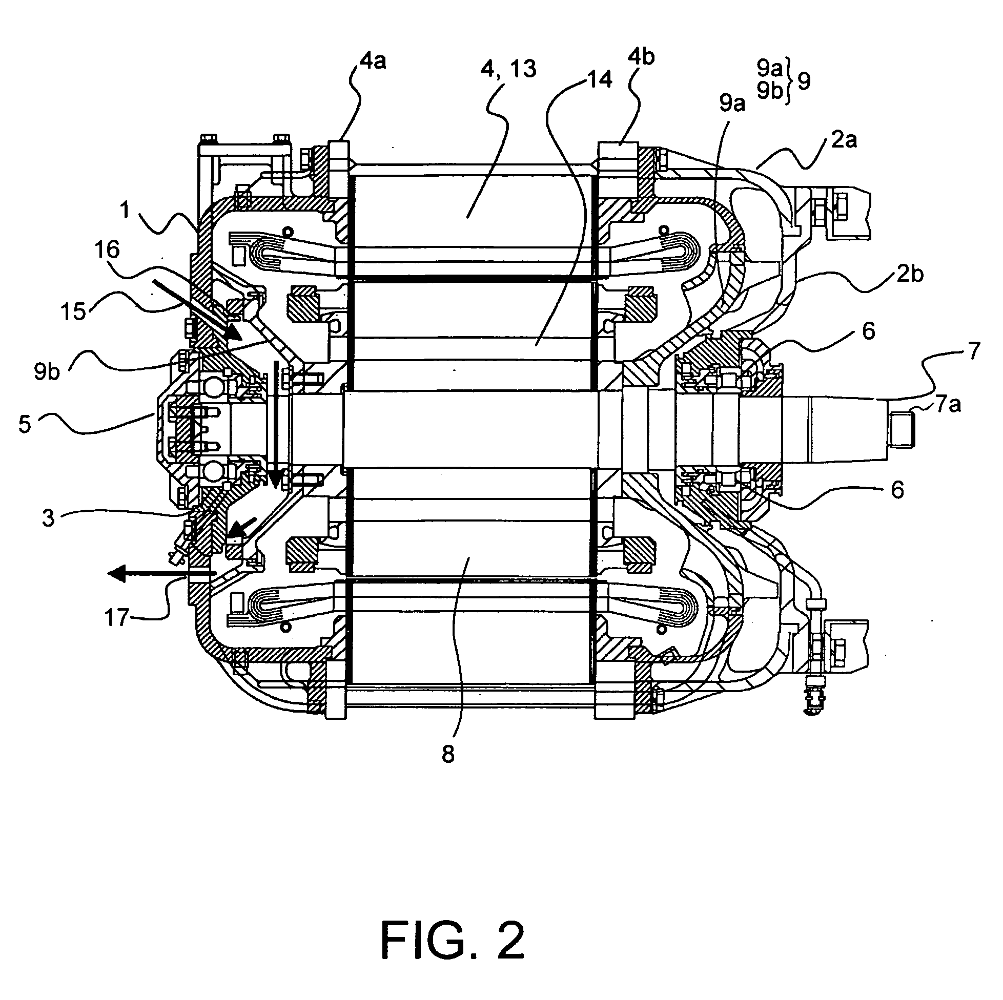
[0072] (First Embodiment)

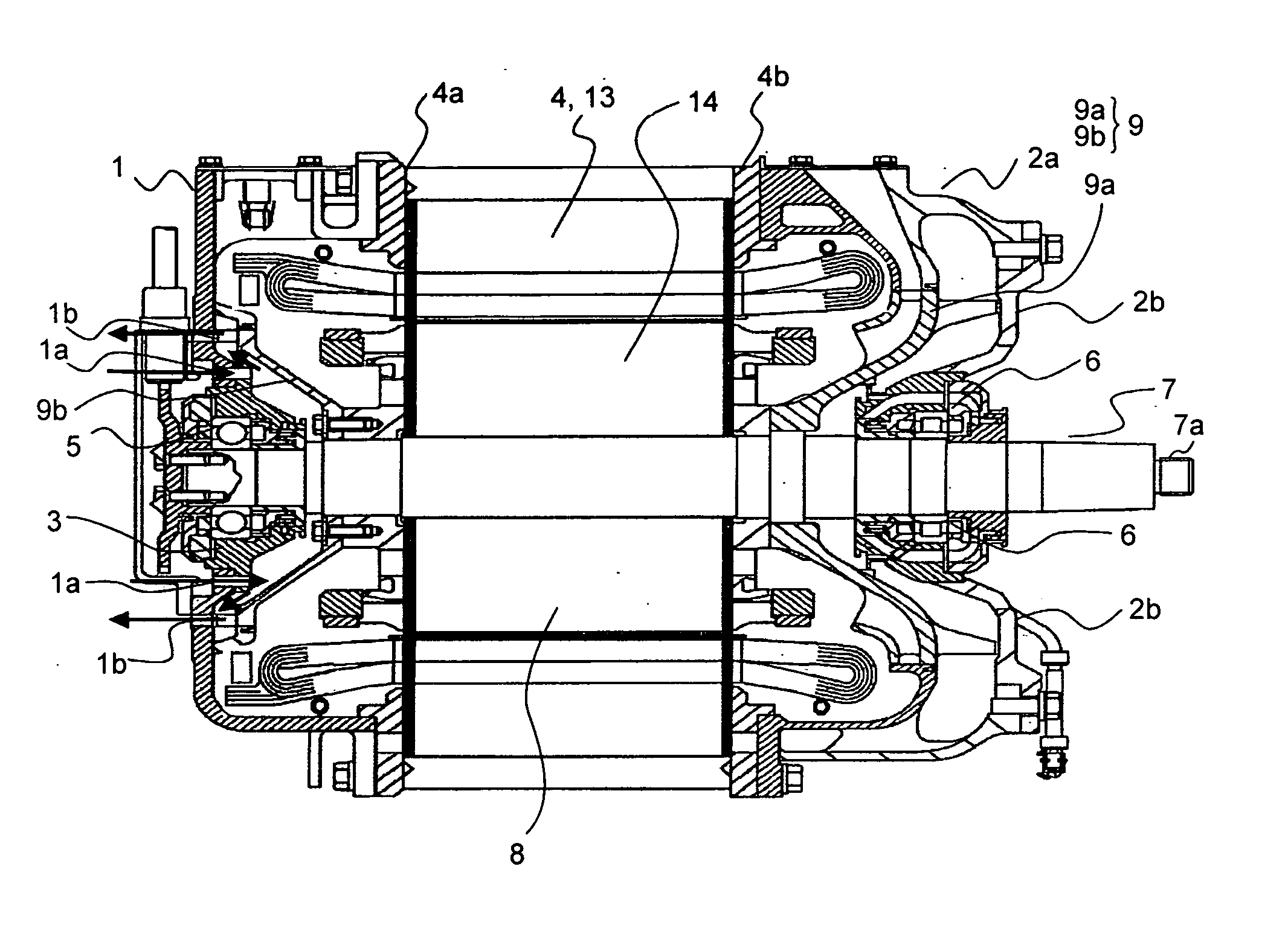
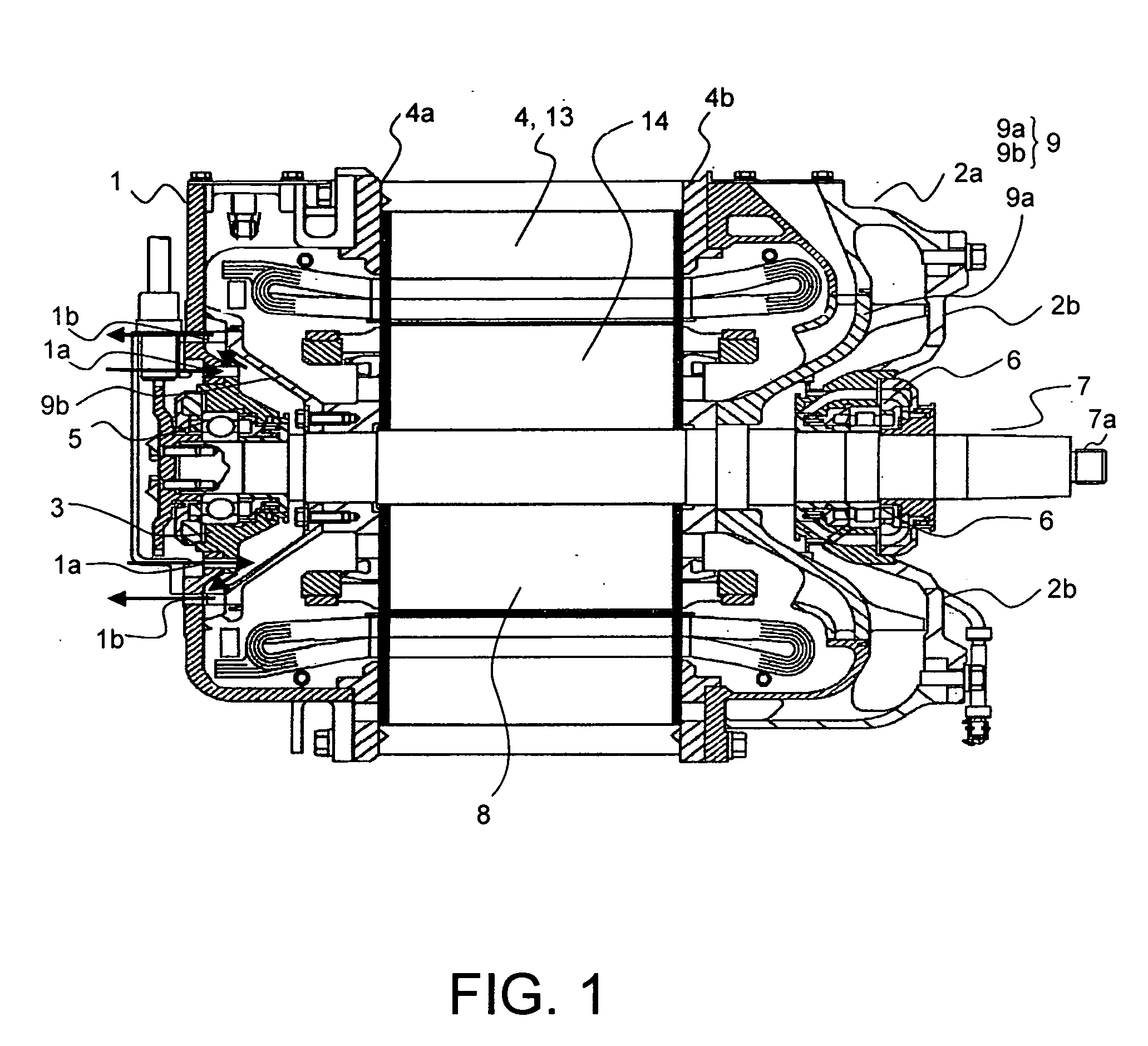
[0073] A rotary electrical machine according to a first embodiment of the invention will be described in detail below with reference to the drawings. FIG. 2 is a cross-sectional view of a rotary electrical machine according to a first embodiment of the invention. FIG. 3 is a front view of a rotary electrical machine according to a first embodiment of the invention.

[0074] A rotary electrical machine according to a first embodiment of the invention is a totally enclosed rotary electrical machine mounted on a rail vehicle.

[0075] In a rotary electrical machine according to a first embodiment of the invention, a stator core 4 supported by a core support 4a and core support 4b is provided between a frame 1 provided on the side opposite to the drive side and an outer peripheral bracket 2a provided on the drive side. An inner peripheral bracket 2b is provided at the inner periphery of the outer peripheral bracket 2a and a housing 3 is provided at the inner periphe...

second embodiment

[0080] (Second Embodiment)

[0081] A rotary electrical machine according to a second embodiment of the invention will be described in detail below with reference to the drawings. FIG. 4 is a front view of a rotary electrical machine according to a second embodiment of the invention. Parts which are structurally the same as those described with reference to FIG. 2 and FIG. 3 are given the same reference symbols and further description thereof is dispensed with.

[0082] The rotary electrical machine of the second embodiment of the invention is characterized in that a partition 18 is provided at the outer periphery of the vanes 9c of the second ventilation fan 9b.

[0083] With a rotary electrical machine constructed in this way, in the same way as in the case of the first embodiment, external air can flow in one direction out from the inlets 15, through the vicinity of the bearing 6 and can be discharged from the outlets 17.

[0084] With a rotary electrical machine constructed in this way, ...


PUM


Abstract

A rotary electrical machine comprises: a stator core; a rotor core arranged at the inner periphery of this stator core; a bracket connected with one end of the stator core; a first bearing arranged by means of the bracket; a frame and a housing connected with the other end of the stator core; a second bearing arranged by means of the housing; a ventilation fan provided between the rotor core and the first bearing, with vanes provided on the outside in the axial direction; a rotor shaft that is freely rotatably supported by the first bearing and second bearing; an inlet provided in the frame or the housing; and an outlet provided in the frame or the housing.

Description

CROSS-REFERENCE TO RELATED APPLICATION [0001] This application claims benefit of priority from Japanese Patent Application No. JP 2005-136671 filed May 9th, 2005, the entire content of which is incorporated by reference herein.BACKGROUND OF THE INVENTION [0002] 1. Field of the Invention [0003] The present invention relates to a rotary electrical machine. [0004] 2. Description of the Related Art [0005] In a typical rail vehicle, a rotary electrical machine is mounted on a chassis suspended below the vehicle body and the vehicle is driven by transmission of the turning effort of this rotary electrical machine to the vehicle wheels through a coupling and gearwheel device. [0006] A totally enclosed rotary electrical machine constituting an example of a prior art rotary electrical machine is described below with reference to the drawings. FIG. 1 is a cross-sectional view of such a prior art totally enclosed rotary electrical machine. [0007] In this specification, the longitudinal directi...

Claims


Application Information

Patent Timeline
IPC IPC(8): H02K9/00H02K5/00H02K5/16
CPCH02K5/1732H02K9/06H02K5/20H02K5/207H02K7/085H02K11/21
Inventor NAGAYAMA, TAKASHIHASHIMOTO, MASATOOKADA, KOJI
Owner KK TOSHIBA
Why Eureka
Try Eureka