Brushed motor position control based upon back current detection

a technology of position control and back current, applied in the direction of motor/generator/converter stopper, dynamo-electric converter control, instruments, etc., can solve the problem of relatively insensitive methods to environmental changes, and achieve accurate indication of then number

Inactive Publication Date: 2006-11-23
MASCO CORP
View PDF49 Cites 722 Cited by
  • Summary
  • Abstract
  • Description
  • Claims
  • Application Information

AI Technical Summary

Benefits of technology

[0006] In a disclosed embodiment of this invention, a back EMF current generated by a brushed electric motor is identified. Applicant has discovered that with each rotation of the motor rotor, as the brushes and commutator move out of engagement, a “ripple” or back EMF force is induced into the motor current. This small ripple can be isolated, or filtered out, of the overall current signal, and counted. By counting the number of occasions of this periodic “ripple,” the present invention is able to provide a very accurate indication of then number of rotations of the rotor, and hence the position of the component. This method is relatively insensitive to environmental changes. Also, the present invention is capable of stopping a motor precisely at any number of intermediate locations.

Problems solved by technology

This method is relatively insensitive to environmental changes.

Method used


Image

  • Brushed motor position control based upon back current detection
  • Brushed motor position control based upon back current detection
  • Brushed motor position control based upon back current detection

Examples


Embodiment Construction

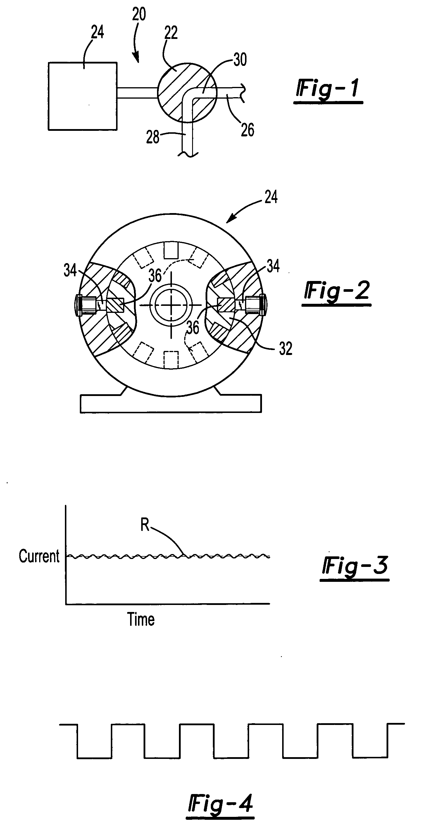
[0013] An electric motor-driven water valve system 20 is illustrated in FIG. 1 highly schematically. As shown, a valve 22 can be rotated by a brushed DC electric motor 24. The valve 22 has a path 30 that selectively communicates a water supply 26 to a downstream user line 28. As the valve 22 is rotated, more and more of the flow path 30 communicates the inlet 26 to the outlet 28. The valve can be rotated to a fully blocked flow position and to a fully open position. Moreover, the valve can be moved to any number of intermediate locations. The valve is shown schematically, and any number of rotary valves are known in the art to provide this basic function.

[0014]FIG. 2 shows a known feature of brushed DC electric motors, which would be true of the brushed DC electric motor 24. As shown, a rotor 32 is driven to rotate by a current induced in a surrounding stator. Brushes 34 periodically contact a commutator portion 36 on the rotor 32. The brushes serve to communicate an electric curre...


PUM


Abstract

Brushed DC electric motors have a rotor with commutator portions moving into and out of contact with brushes. As each of these contacts end, a back EMF force is induced into a main current supply signal. The number of these periodic forces can be counted and utilized to identify the position of the component being rotated by the DC electric motor. This method is relatively insensitive to environmental changes, and thus more accurate than the existing art.

Description

BACKGROUND OF THE INVENTION [0001] This application relates to a method of monitoring the position of a component driven by a DC brushed electric motor, which counts a periodic back electromotive force. [0002] DC motors are utilized in various industries to drive any number of components between different positions. As one volume application, DC motors are utilized in automotive applications to move windows, etc. For a number of reasons, the position of the component driven by the electric motor is desirably detected. The end of travel position must be detected such that current flow to the motor can be stopped. In motors utilized in automotive application, the motor current to the windows is monitored. The motor current would increase at the end of travel position of a window, for example. Motor current is a function of torque, which would increase when the window reaches it end of travel position. [0003] Unfortunately, motor current and torque can vary greatly based upon age of th...

Claims


Application Information

Patent Timeline
Patent Type & Authority Applications(United States)
IPC IPC(8): H02P7/06
CPCG01R31/343
Inventor IOTT, JEFFREYBURKE, DAVID
Owner MASCO CORP
Why Eureka
Try Eureka