Optical alignment apparatuses and methods for optics used in absorption cell spectrometers

an absorption cell and optic alignment technology, applied in the field of optic alignment apparatuses and optics used in absorption cell spectrometers, can solve problems such as placing design restrictions, and achieve the effect of maximizing the light coming through the correct aperture and easy adjustment of angl

Active Publication Date: 2017-05-18
DUVAS TECH
View PDF5 Cites 22 Cited by
  • Summary
  • Abstract
  • Description
  • Claims
  • Application Information

AI Technical Summary

Benefits of technology

[0005]Apparatuses and methods for aligning optical elements in a White cell are discussed below. Three concave mirrors in a White cell have to be set to precise angles to ensure the correct number of passes through the cell. In White's original cell, a single row of spots is used, which places restrictions on the design. In the cell described in commonly owned U.S. Provisional Patent Application No. 62 / 238,537 (537 application) filed on Oct. 7, 2015, and titled “DESIGN OF INPUT AND OUTPUT OPTICAL SYSTEMS FOR MULTIPASS SPECTROSCOPIC ABSORPTION CELLS,” two rows of spots are used, which improves light throughput. The '537 Application discusses the design of the cell, including the sensitivity to mirror angles. In particular the toe-in angle of the two small mirrors is discussed. In addition, these two mirrors need to be set to a further angle at right angles to the toe in. Furthermore the single large mirror needs to be set to twice this angle. The alignment fixture described herein makes use of the imaging properties of a concave mirror, and provides for aligning such mirrors.
[0007]Therefore, by putting further apertures in calculated positions in the same plane is the laser aperture and of the same diameter (0.5 mm) the mirrors can easily be adjusted for angle to maximize the light coming through the correct aperture.

Problems solved by technology

In White's original cell, a single row of spots is used, which places restrictions on the design.

Method used


Image

  • Optical alignment apparatuses and methods for optics used in absorption cell spectrometers
  • Optical alignment apparatuses and methods for optics used in absorption cell spectrometers
  • Optical alignment apparatuses and methods for optics used in absorption cell spectrometers

Examples


Embodiment Construction

[0031]For purposes of reading the description of the various embodiments below, the following descriptions of the sections of the specification and their respective contents may be helpful:

[0032]Section A describes a network environment and computing environment which may be useful for practicing embodiments described herein.

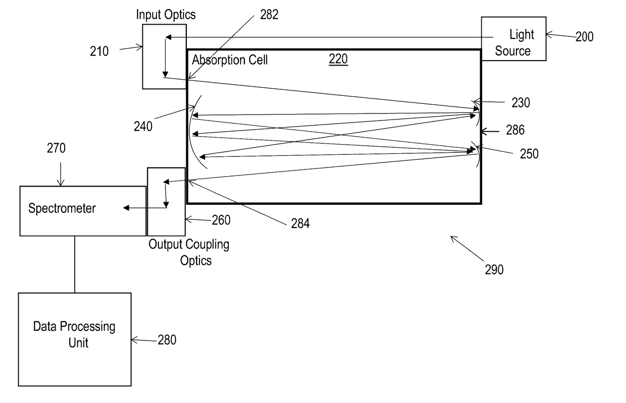
[0033]Section B describes systems and methods for detecting gas and vapor species using a spectrometer and a multi-pass absorption cell.

[0034]Section C describes systems and method for alignment of optics used in the multi-pass absorption cell.

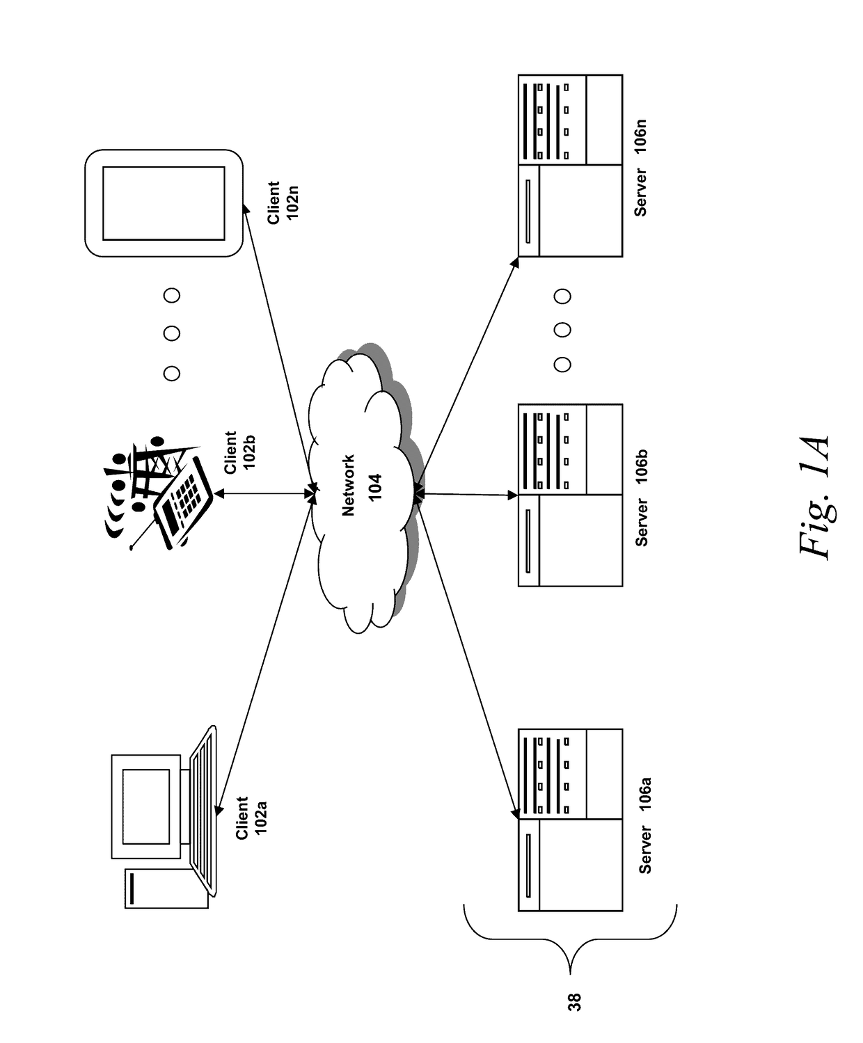
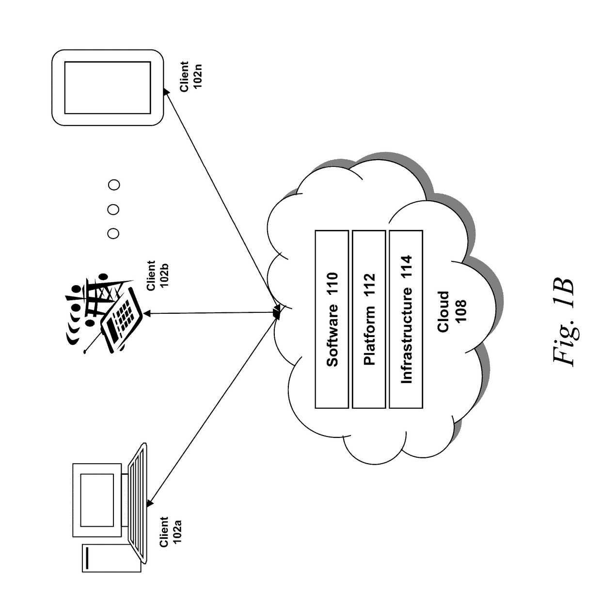
[0035]A. Computing and Network Environment

[0036]Prior to discussing specific embodiments of the present solution, it may be helpful to describe aspects of the operating environment as well as associated system components (e.g., hardware elements) in connection with the methods and systems described herein. Referring to FIG. 1A, an embodiment of a network environment is depicted. In brief overview, the network environment i...


PUM

PropertyMeasurementUnit
focal lengthaaaaaaaaaa

Abstract

Systems and methods of the present disclosure are directed to optics used in absorption cell spectrometers. The absorption cell includes a plurality of mirrors arranged in a manner such that a detection light traverses multiple passes through the fluid within the absorption cell. In some implementations, the detection light is reflected by the plurality of mirrors to form optical paths in more than one plane. In some implementations, the orientation of the mirrors are aligned with specific orientations to provide the desired optical path to the detection light. In one or more embodiments, an alignment apparatus can be used to pre-align the mirrors before they are placed within the absorption cell. The alignment apparatus includes an aperture plate and an adjustable mount to mount one or more mirrors. The mirrors are aligned based on reflected images on the aperture plate laser light incident on the mirrors.

Description

CROSS-REFERENCE TO RELATED APPLICATIONS[0001]The present Application for Patent claims priority to U.S. Provisional Application No. 62 / 254,881 entitled “WHITE CELL OPTICAL ALIGNMENT METHOD AND FIXTURE,” filed Nov. 13, 2015, which is incorporated herein in its entirety.FIELD OF THE DISCLOSURE[0002]The present disclosure is generally directed to spectroscopy. In particular, the present disclosure describes techniques for alignment of optics used in abruption cell spectroscopy.BACKGROUND OF THE DISCLOSURE[0003]Optical spectrometers measure the presence or absence of light at various wavelengths, and when combined with a known light source, can be used to identify various species of gas or liquid by observing which wavelengths are absorbed. Each species of gas or liquid has a unique spectral absorption characteristics and therefore can be uniquely identified by its absorption signature. Absorption cell spectrometers include several mirrors with specific relative orientations to allow mu...

Claims


Application Information

Patent Timeline
Patent Type & Authority Applications(United States)
IPC IPC(8): G02B7/182G02B17/06G02B5/08G01N21/03G01J3/02G01J3/42G01N21/33G02B27/48G02B5/10
CPCG02B7/1822G02B27/48G02B17/0642G02B5/0891G02B5/10G01N2201/12G01J3/42G01N21/33G01J3/0264G01N21/031G01J3/0289G01J3/0208G01J3/0237G02B17/004G02B27/62
Inventor SAWYERS, CRAIG
Owner DUVAS TECH
Why Eureka
Try Eureka