Control device for electronic appliance and control method of the electronic appliance

Active Publication Date: 2008-11-20
JVC KENWOOD CORP A CORP OF JAPAN
View PDF3 Cites 20 Cited by
  • Summary
  • Abstract
  • Description
  • Claims
  • Application Information

AI Technical Summary

Benefits of technology

[0009]An object of the present invention is to provide a control device for an electronic appliance and a control method of the electronic appliance in which the number of clapping sounds can correctly be recognized in view of intervals between generated clapping sounds that depend on a

Problems solved by technology

When the electronic appliance is distant from the operator, the control is very laborious.
However, if the RC is not near to the operator, the operator has to find out a place where the RC is present, and fetch the RC.
However, in a case where the apparatus is not continuously controlled and it is desired to readily control any one operation, for example, in a case where a power supply only is turned on first of all, the operator feels troublesome.
Furthermore, there often occurs a situation in which the use of the RC is desired but th

Method used


Image

  • Control device for electronic appliance and control method of the electronic appliance
  • Control device for electronic appliance and control method of the electronic appliance
  • Control device for electronic appliance and control method of the electronic appliance

Examples


Example

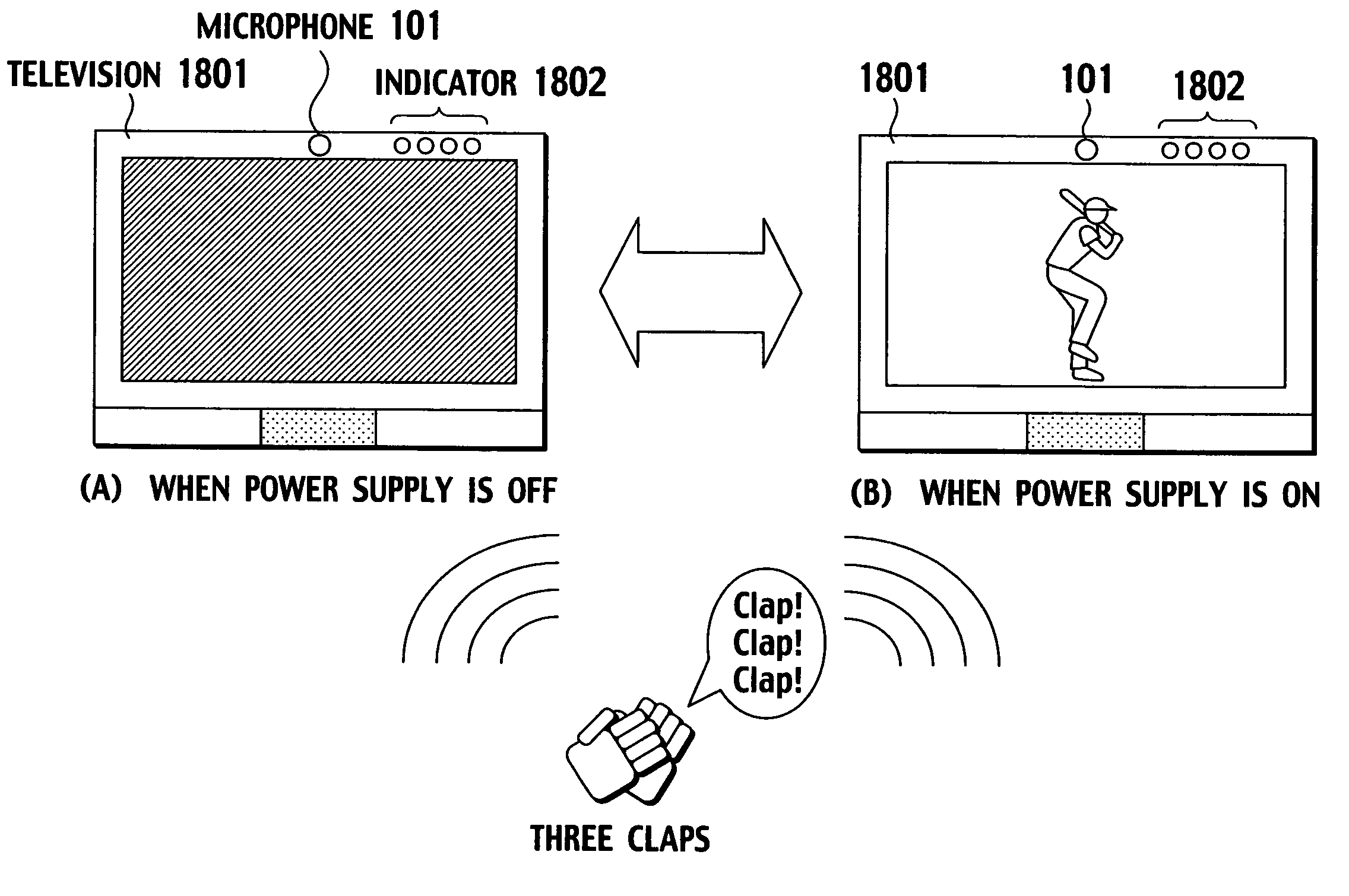
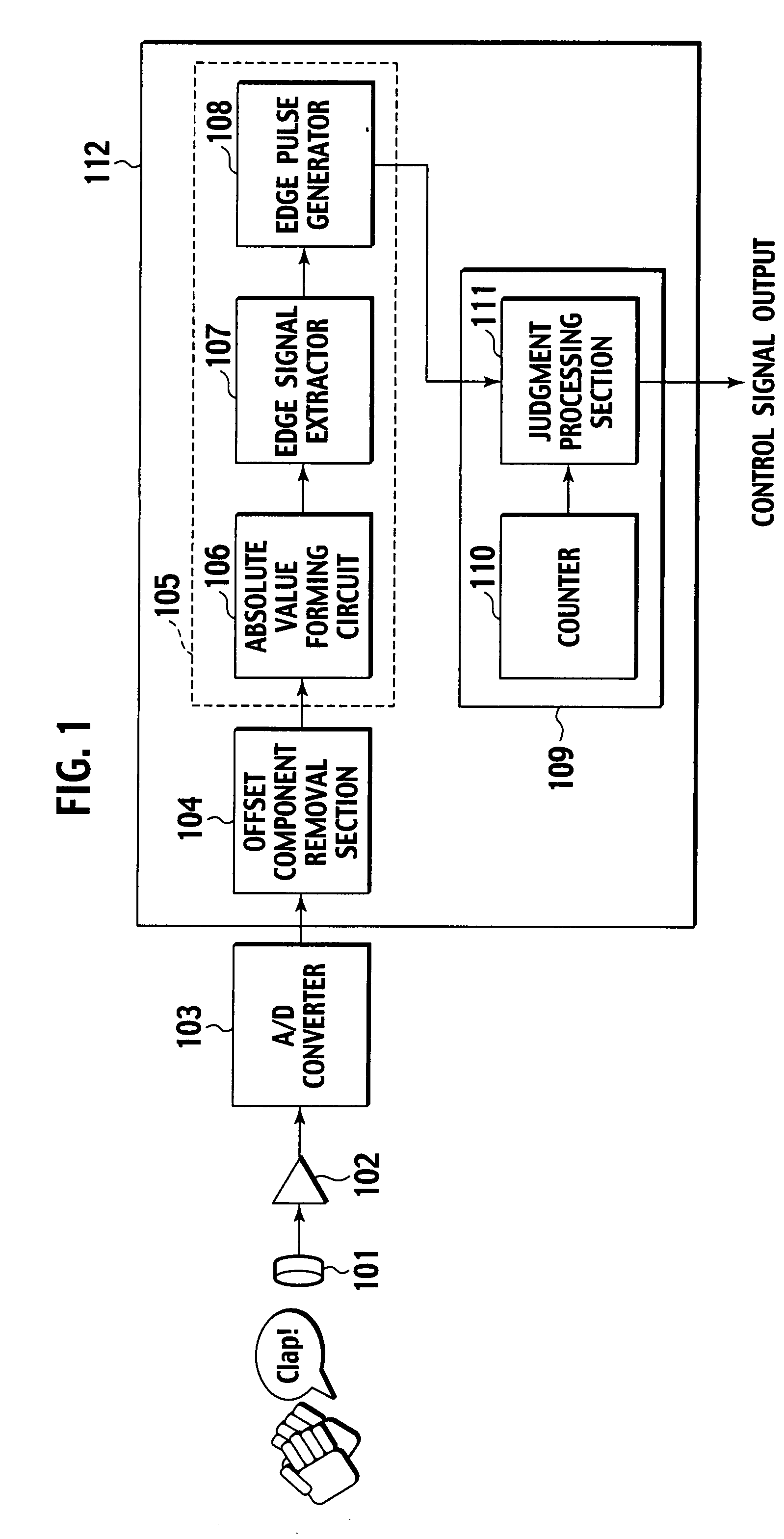
[0050]FIG. 1 is a block diagram showing a first embodiment of a control device for an electronic appliance according to the present invention. The control device for the electronic appliance is disposed in the electronic appliance, and realizes a remote operation of the electronic appliance by an operator. The control device for the electronic appliance of the first embodiment controls the electronic appliance by a series of sound waves (e.g., clapping sounds) which are generated at predetermined time intervals by the operator.

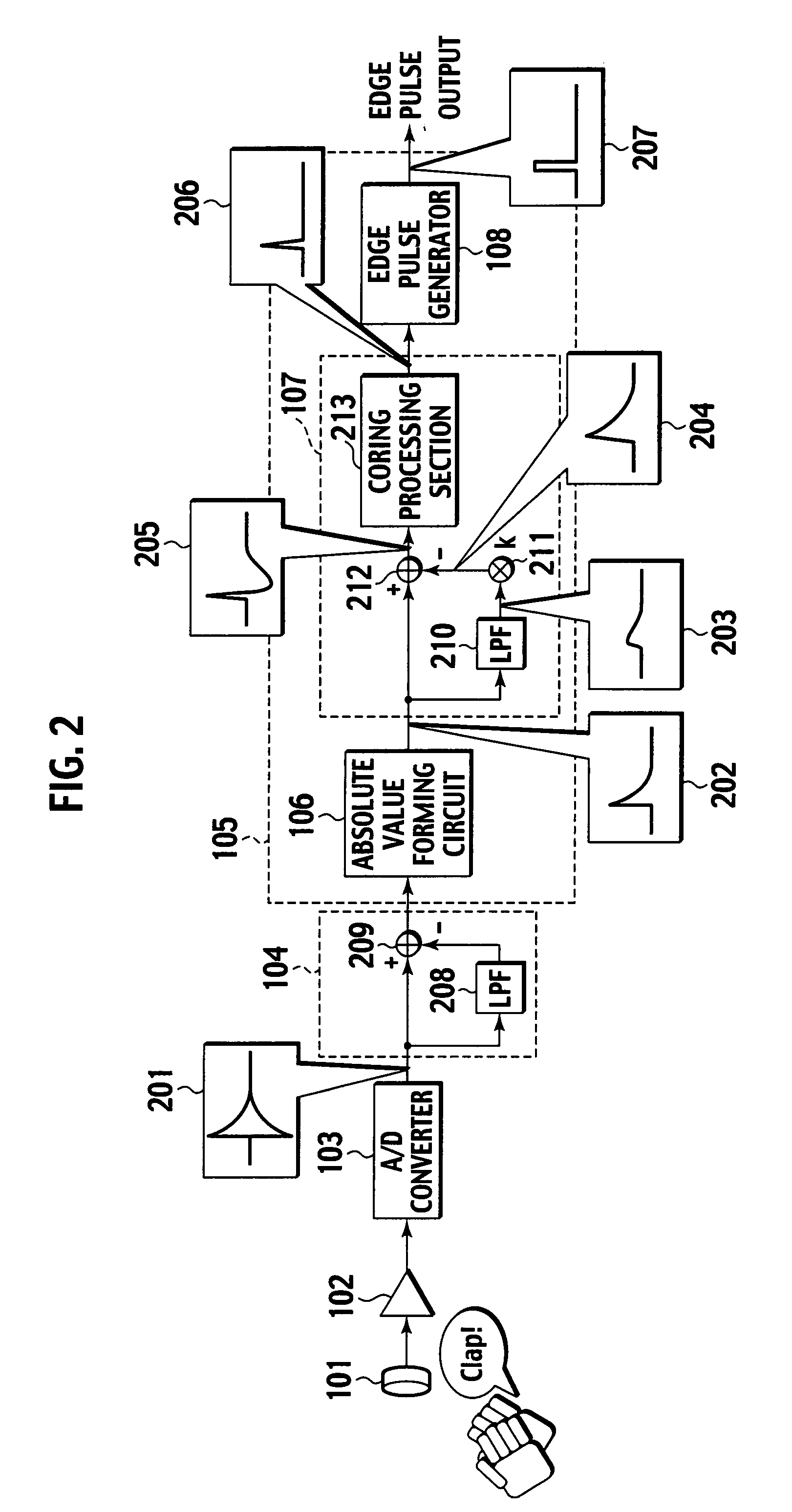
[0051]The control device for the electronic appliance of the first embodiment includes a microphone (hereinafter abbreviated as the MC) 101 which detects operator's clapping sound, an amplifier 102 which amplifies an analog voice signal from the MC 101, an A / D converter 103 which converts the analog voice signal output from the amplifier 102 into a digital signal; and a central processing unit (CPU) 112 which processes the digital voice signal output from the ...

Example

Second Embodiment

[0122]Next, a second embodiment of the present invention will be described. In a case where clap control of the present invention is performed, when a large noise other than a clapping sound is present at a surrounding area, the clapping sound is buried in the surrounding noise and might not be detected. For example, in a case where music is listened at a high volume, when a sound similar to the clapping sound (in an amplitude value, a frequency band or the like) rings in the music, the sound is recognized as the clapping sound, and an erroneous operation might be caused.

[0123]Here, a state in which there is a possibility that inability to control an electronic appliance by claps or the erroneous operation is caused by such a surrounding sound other than the clapping sound will be referred to as a noise state.

[0124]Here, the second embodiment is constituted so that, in a case where it is judged that a state is the noise state, the control by the claps is prohibited....

Example

Third Embodiment, Fourth Embodiment

[0134]Next, third and fourth embodiments of the present invention will be described. It can be said that the edge signal extractor 107 of the first embodiment separates a noise which is a low-frequency component from a clapping sound which is a high-frequency component by use of a low pass filter (LPF), but the third and fourth embodiments are constituted so that an input sound is divided into a plurality of frequency bands, and a necessary component and an unnecessary component are further distinguished from each other.

[0135]Since the clapping sound indicates an impulse waveform, the sound has signal components over almost all of the frequency bands. When the input sound is divided into a plurality of bands with a pass filter by use of this characteristic and the sounds are subjected to clapping sound detection processing as in the first embodiment, the clapping sound can be distinguished from another sound such as a sound which exists in an only ...


PUM


Abstract

An electronic appliance includes a microphone which detects a clapping sound, an edge signal extractor, an edge pulse generator and a judgment processing circuit. The judgment processing circuit generates a first gate having a first time width to detect whether or not a second clapping sound has been generated after elapse of a first predetermined time from a first time when the microphone detects a first clapping sound and the edge pulse generator generates the first edge pulse corresponding to the first clapping sound. Subsequently, the judgment processing circuit generates a second gate having a second time width to detect whether or not a third clapping sound has been generated after elapse of a second predetermined time from a second time when the edge pulse generator generates the second edge pulse corresponding to the second clapping sound.

Description

BACKGROUND OF THE INVENTION[0001]1. Field of the Invention[0002]The present invention relates to a control device for an electronic appliance and a control method of the electronic appliance. More particularly, it relates to a control device for an electronic appliance and a control method of the electronic appliance in which the electronic appliance to be controlled from a remote area with a remote controller is controlled without using any remote controller.[0003]2. Description of the Related Art[0004]Electronic appliances such as television receiver, audio system and air conditioner presently used are usually controlled by touching an operation button of a main body or by using a remote controller (hereinafter referred to as the RC). In the former case, an operator has to come close to the main body of the electronic appliance as a control target. When the electronic appliance is distant from the operator, the control is very laborious. This problem is solved using the RC as in t...

Claims


Application Information

Patent Timeline
IPC IPC(8): G10K11/00
CPCG08C23/02
Inventor OHGURI, HIROKAZUKITAURA, MASAHIRO
Owner JVC KENWOOD CORP A CORP OF JAPAN
Why Eureka
Try Eureka