Method for producing map images of surface sea current velocity vectors and altimetric radar system using the method

a technology of surface sea current and velocity vector, which is applied in the direction of reradiation, measurement devices, instruments, etc., can solve the problems of low precision, inability to map the speed of mobile targets, and inability to study coastal regions with conventional altimeters or wsoa systems, etc., to eliminate the disadvantages of large variability and eliminate the effect of disadvantages

Inactive Publication Date: 2006-11-23
EUROPEAN SPACE AGENCY
View PDF3 Cites 11 Cited by
  • Summary
  • Abstract
  • Description
  • Claims
  • Application Information

AI Technical Summary

Benefits of technology

[0014] The purpose of this invention is to eliminate these disadvantages. Thus, one purpose of the invention is to produce map images of current velocity vectors at the surface sea, in regions with a large variability both in terms of space and time, such as coastal regions.

Problems solved by technology

They cannot be used for mapping the speed of mobile targets.
However, neither conventional altimeters nor the WSOA system are capable of studying coastal regions due to their low precision and insufficient time sampling, and in any case are unsuitable for the large variability of these regions both in space and in time.
Therefore, this system cannot be used to obtain a map of surface current velocities.
If this system is onboard a satellite at an altitude of several hundred km, the precision obtained is unsuitable for the study of surface currents in coastal regions.
However, application of this constraint can degrade performances of the system concerning measurement of altitudes.

Method used


Image

  • Method for producing map images of surface sea current velocity vectors and altimetric radar system using the method
  • Method for producing map images of surface sea current velocity vectors and altimetric radar system using the method
  • Method for producing map images of surface sea current velocity vectors and altimetric radar system using the method

Examples


Embodiment Construction

)

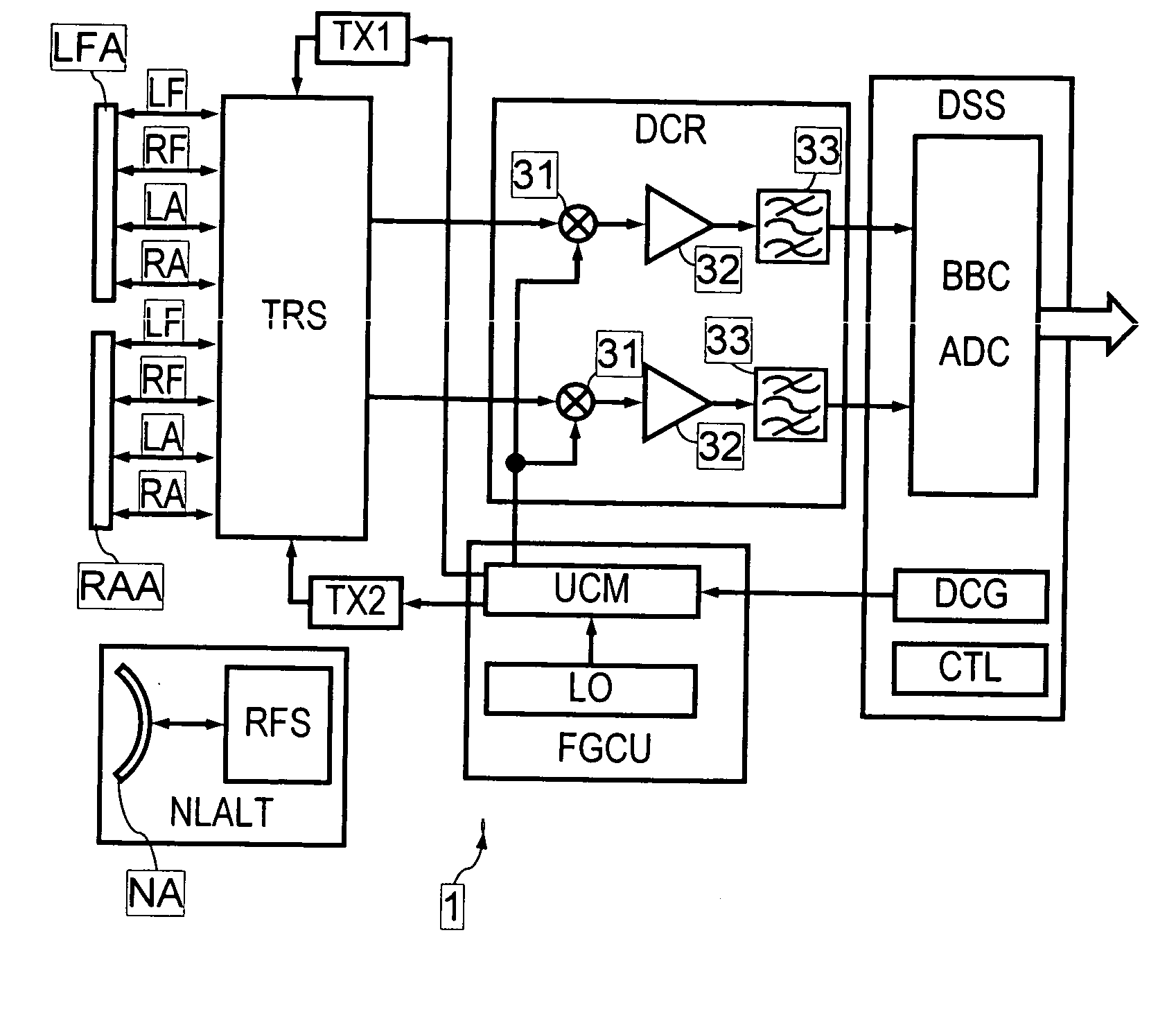
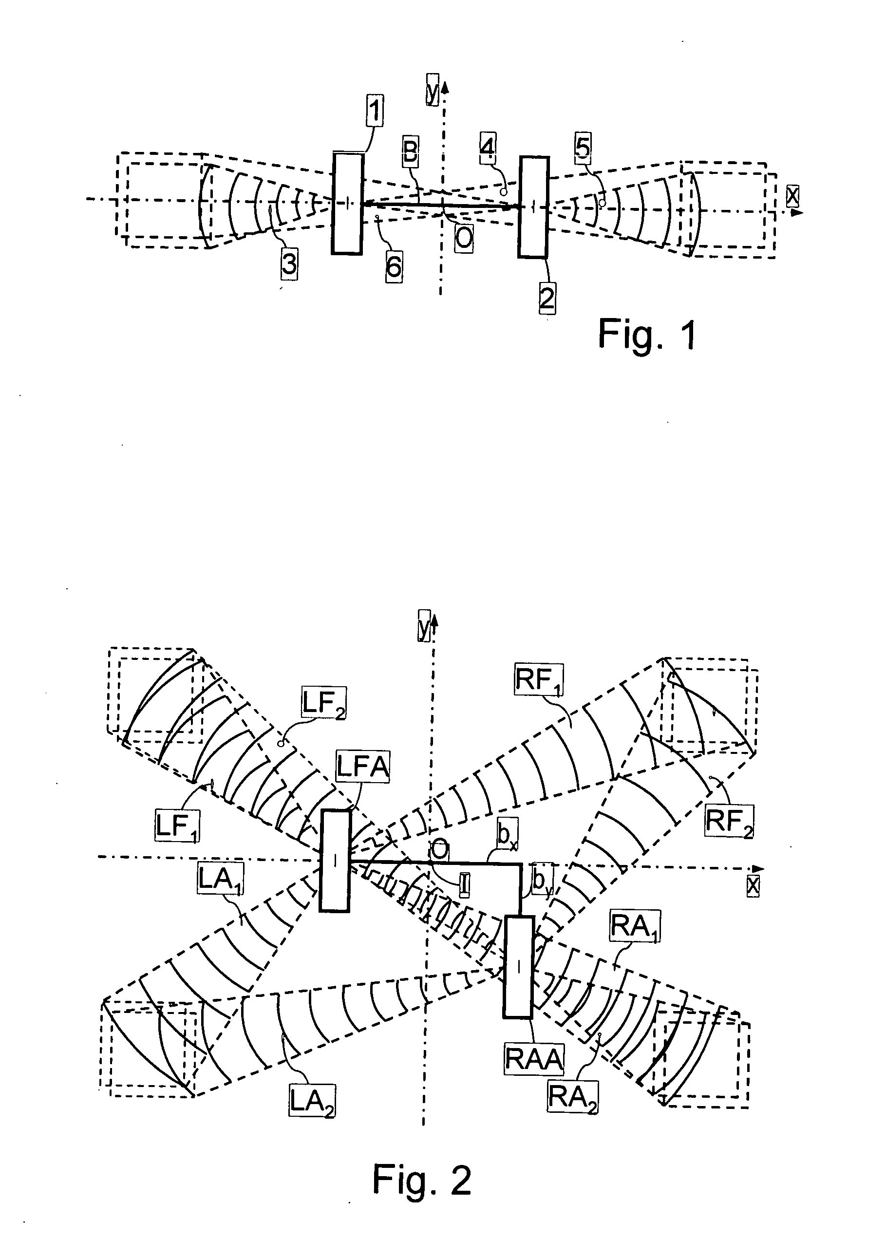
[0046]FIG. 2 shows an interferometric radar system according to the invention, this system being onboard a mobile platform (aircraft or satellite) moving along a track with a ground trace 10 along an axis Oy. This system comprises two antennas LFA, RAA at a spacing equal to a distance bx along a horizontal direction Ox perpendicular to the Oy axis.

[0047] According to the invention, the LFA, RAA antennas are also at a spacing equal to a distance by along the Iy direction of the track, where I is the mid-point of the antenna base along the Ix direction perpendicular to the track. Each of the two antennas LFA, RAA emits 4 beams RFi, LFi, RAi, LAi (i=1 and 2 respectively for the two antennas), namely a right forward beam RFi (right of the track), a left forward beam LFi, a right aft beam RAi, a left aft beam LAi. Although FIG. 2 shows a left forward antenna LFA and a right aft antenna RAA, a right forward antenna and a left aft antenna could equally well be envisaged.
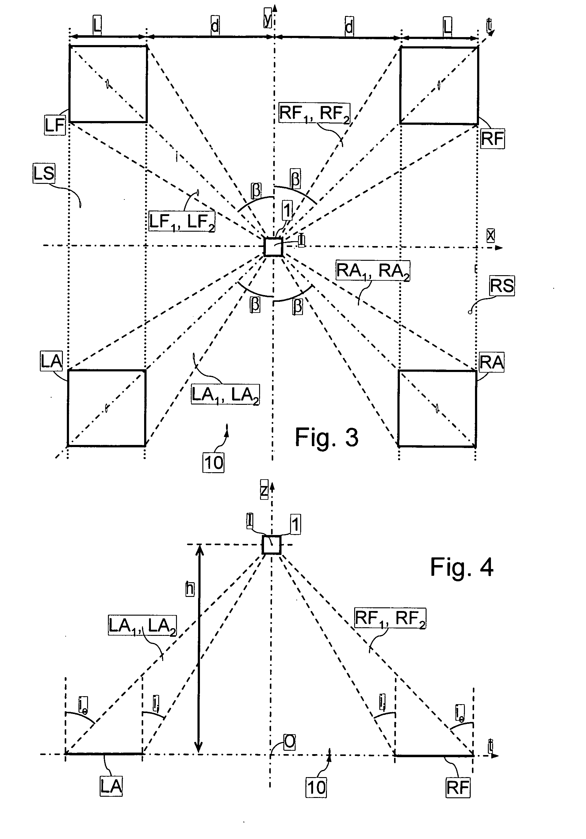
[0048] In FIG. 3...


PUM


Abstract

A method for producing map images of current velocity vectors at the surface sea is described in which beams of electromagnetic waves are emitted towards the surface using a system, towards the left forward and right forward sides of the track of the system, and towards the left aft and right aft sides of the track, from two antennas at a distance from each other along the direction of the track and along a direction perpendicular to the track, and values of roll angle and length of the antenna base connecting the two antennas are determined using differential interferometries applied to the electromagnetic waves reflected by the surface between beams emitted forwards and backwards, the map images being built up using an along-track type differential interferometry, using roll angle and antenna base length values obtained.

Description

BACKGROUND OF THE INVENTION [0001] (1) Field of the Invention [0002] This invention relates to the domain of altimetric measurements and more particularly the determination of surface ocean currents using altimetric radar onboard satellites. [0003] It is particularly but not exclusively applicable to the study of surface sea currents in coastal regions. [0004] (2) Prior Art [0005] Such a study is desirable for many reasons. Coastal waters are extremely dynamic regions in which submarine relief and particularly navigation channels can vary significantly over relatively short periods. Furthermore, the study of surface currents provides a means of determining the distribution of pollutants and the flow of cold polar water and water derived from ice melt. [0006] Conventional satellite altimetric radar can scan a relatively narrow band also called a “swath” on the earth's surface, typically a few kilometres wide. This means that only a small fraction of the ocean surface can be observed ...

Claims


Application Information

Patent Timeline
Patent Type & Authority Applications(United States)
IPC IPC(8): G01S13/90
CPCG01S13/9035G01S13/89G01S13/904G01S13/9023
Inventor BUCK, CHRISTOPHER HEREWARD
Owner EUROPEAN SPACE AGENCY
Why Eureka
Try Eureka