Plastic optical element, mold for forming the plastic optical element, light scanning device and image forming apparatus having the light scanning device

a technology of plastic optical elements and molds, which is applied in the field of plastic optical elements, molds for forming plastic optical elements, light scanning devices and image forming apparatuses having light scanning devices, can solve the problems of large space required for arrangement of plurality of scanning devices, low farm accuracy of transfer surfaces, and low form accuracy of forming pieces or non-transfer surfaces, etc., to achieve compact and high accuracy arrangement, reduce the load on the deflector, and high accuracy

Active Publication Date: 2006-11-23
RICOH KK
View PDF8 Cites 19 Cited by
  • Summary
  • Abstract
  • Description
  • Claims
  • Application Information

AI Technical Summary

Benefits of technology

[0038] With the above structure, it is possible to accomplish compact and high accuracy arrangement of the plastic optical elements in the light scanning device, and provide a compact, inexpensive and high accuracy plastic optical element capable of reducing a load on the deflector and forming an image having high quality.

Problems solved by technology

However, a large space is required for arrangement of the plurality of scanning devices.
For example, the transfer surface has low farm accuracy for the reason that when the lens includes a shape having a biased wall, a cooling velocity of the resin by a difference of thickness of the optical element or lens is different every each location on the optical element to generate a different amount of volume contraction.
However, with demands to achieve further high quality image in recent years, there is a significant problem on a process that the transfer surface adjacent the aura defining the gap forcibly between the resin and the cavity forming piece or the surface including the non-transfer surface has low form accuracy.
The non-transfer surface is difficult to control in depth.
If the dopth is set over an optical effect range, the optical element disturbs lens function.
Accordingly, in a light scanning device in which conventional plastic optical element are disposed to face each other in both sides of a light source section, there is a problem that relative deflection of the optical axes of the plastic optic elements occur, the polygonal mirror has a large size, the load of the motor to rotate the polygonal mirror increases, and the light scanning device and an image forming apparatus become a large size to lower the quality of an image to be formed.
Furthermore, the conventional plastic optical element has the same problem as in the above-mentioned light device.

Method used


Image

  • Plastic optical element, mold for forming the plastic optical element, light scanning device and image forming apparatus having the light scanning device
  • Plastic optical element, mold for forming the plastic optical element, light scanning device and image forming apparatus having the light scanning device
  • Plastic optical element, mold for forming the plastic optical element, light scanning device and image forming apparatus having the light scanning device

Examples


Embodiment Construction

[0060] Preferred embodiments of the present invention will be explained in detail with reference to the accompanying drawings below.

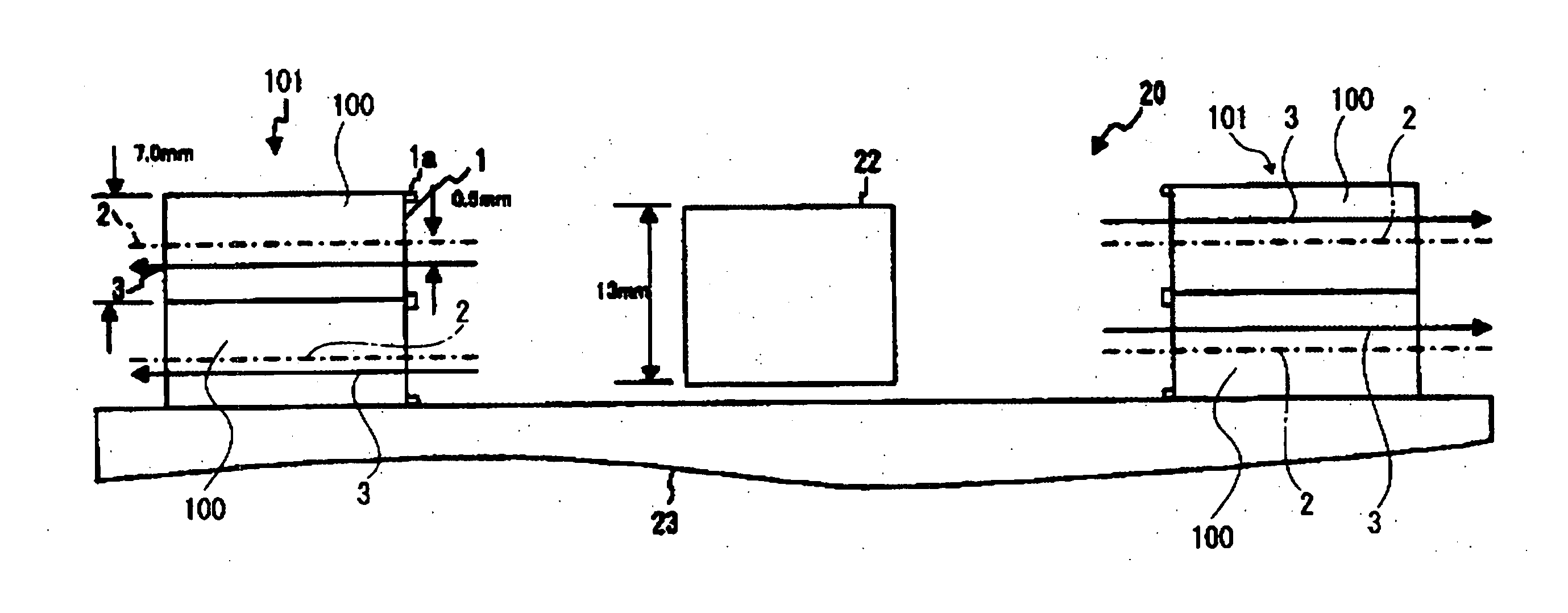
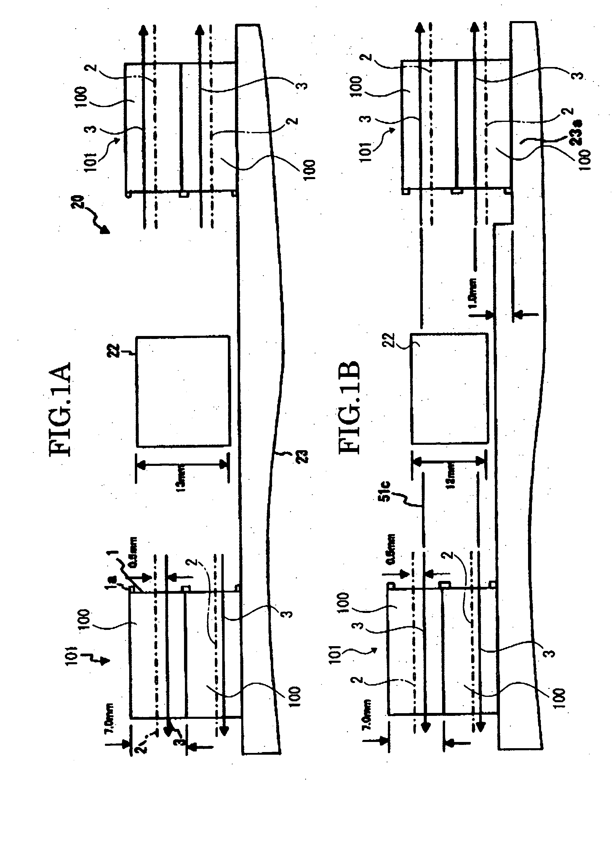
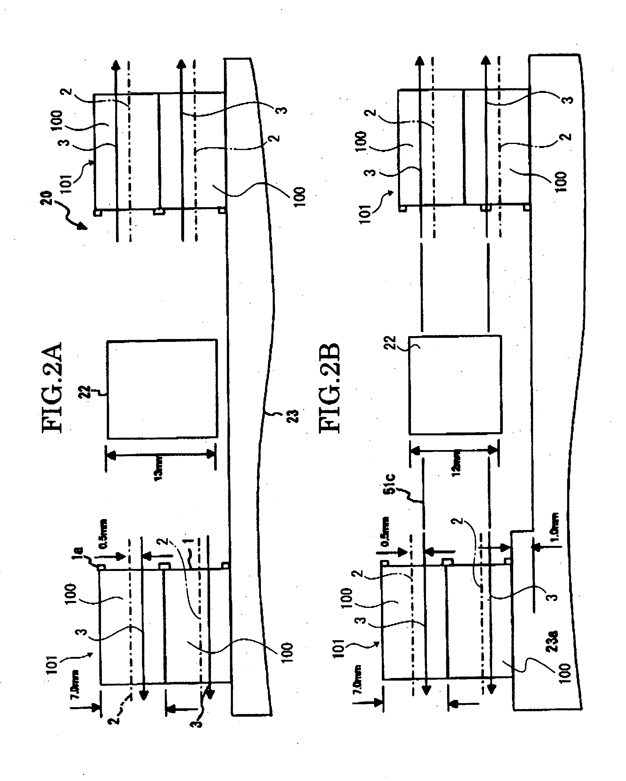
[0061]FIGS. 1A and 1B illustrate a first embodiment of a light scanning device 20 according to the present invention and FIG. 3 illustrates one embodiment of a plastic optical element 100 according to the present invention, which is applied to the light scanning device 20.

[0062] The plastic optical element 100 is disposed to face a light source section and configured to collect and scan beam emitted from the light source section.

[0063] For example, the light source section includes at least one light source 21 to emit the beam and a deflection section 22 receiving the beam from the light source 21 and reflecting the beam and is configured to direct the reflected beam to the plastic optical element 100, as shown in FIGS. 12A and 13A. The deflection section 22 has, for example, a polygonal mirror.

[0064] The plastic optical element 100 is configured to...


PUM

PropertyMeasurementUnit
thicknessaaaaaaaaaa
thicknessaaaaaaaaaa
thicknessaaaaaaaaaa

Abstract

A plastic optical element being configured to collect and scan a beam emitted from at least one light source section, and including a transfer surface which extends in a principal direction corresponding to a scanning direction of the beam and has a curved surface formed to extend into a circular-arc shape in a secondary direction perpendicular to the principal scanning direction, the transfer surface having an optical aids disposed to shift from an outer center of the transfer surface in the secondary scanning direction, and a center of curvature of the curved surface being disposed on the optical axis.

Description

CROSS-REFERENCE TO THE RELATED APPLICATION [0001] This application is based on and claims the priority benefit of Japanese Patent Application No. 2005-112350, filed on Apr. 8, 2005, the disclose of which is incorporated herein by reference in its entirety. BACKGROUND OF THE INVENTION [0002] 1Field of the Invention [0003] The present invention relates to a plastic optical element configured to collect and scan beam emitted from a light source, a mold or forming the plastic optical element, a light scanning device including the plastic optical element and configured to scan beam emitted from at least one light source section and form an image based on image information, and an image forming apparatus having the light scanning device, which is, for example, an optical instrument such as a video camera or the like, a copying machine or forming a toner image trough an image forming process of an electrophotographic method, a facsimile device, a printer or a complex machine thereof, or th...

Claims


Application Information

Patent Timeline
Patent Type & Authority Applications(United States)
IPC IPC(8): G02B26/08
CPCB29C45/174G02B13/0005B29D11/00B29C45/56
Inventor HAYASHI, EIICHI
Owner RICOH KK
Why Eureka
Try Eureka