Inter-domain routing technique using MPLS

a routing technique and inter-domain technology, applied in the field of path control technique of a network, can solve the problems of unstable mutual operation of mpls, complex protocol, and a lot of efficiency problems

Active Publication Date: 2006-11-23
FUJITSU LTD
View PDF8 Cites 79 Cited by
  • Summary
  • Abstract
  • Description
  • Claims
  • Application Information

AI Technical Summary

Problems solved by technology

A conventional path control technique for a network has following problems: (a) it is impossible to detect routes being congested, in advance; (b) symmetric routing in uplink and downlink cannot be forcibly carried out; (c) it is impossible to reflect the state of a server in routing; (d) it requires a load and / or time to check the states of routes; and (e) it requires a load and / or time to carry out a dynamic processing.
Especially, because the Internet, which has come into wide use in recent years, has developed without considering the entire efficiency improvement, it has a lot of problems in efficiency.
For example, as for the routing and switching, because autonomous operations are assumed, the protocol is complicated, and there are a lot of case in which the state in the network is not unknown.
However, because (a) different routing policies are used for respective domains; (b) an administrator requests not to open the state of a network to other domains; (c) the mutual operation of MPLS may be unstable or the like, MPLS has not been applied to routing between different domains.
However, this publication does not study MPLS.
Moreover, because in this technique, routing is carried out according to a routing protocol, a large amount of load is necessary for routers.
Therefore, there are problems in which in communication between domains, to which MPLS is applied, it is impossible to carry out the optimum routing of End-to-End, to avoid network congestion, and to carry out symmetric routing.

Method used


Image

  • Inter-domain routing technique using MPLS
  • Inter-domain routing technique using MPLS
  • Inter-domain routing technique using MPLS

Examples


Embodiment Construction

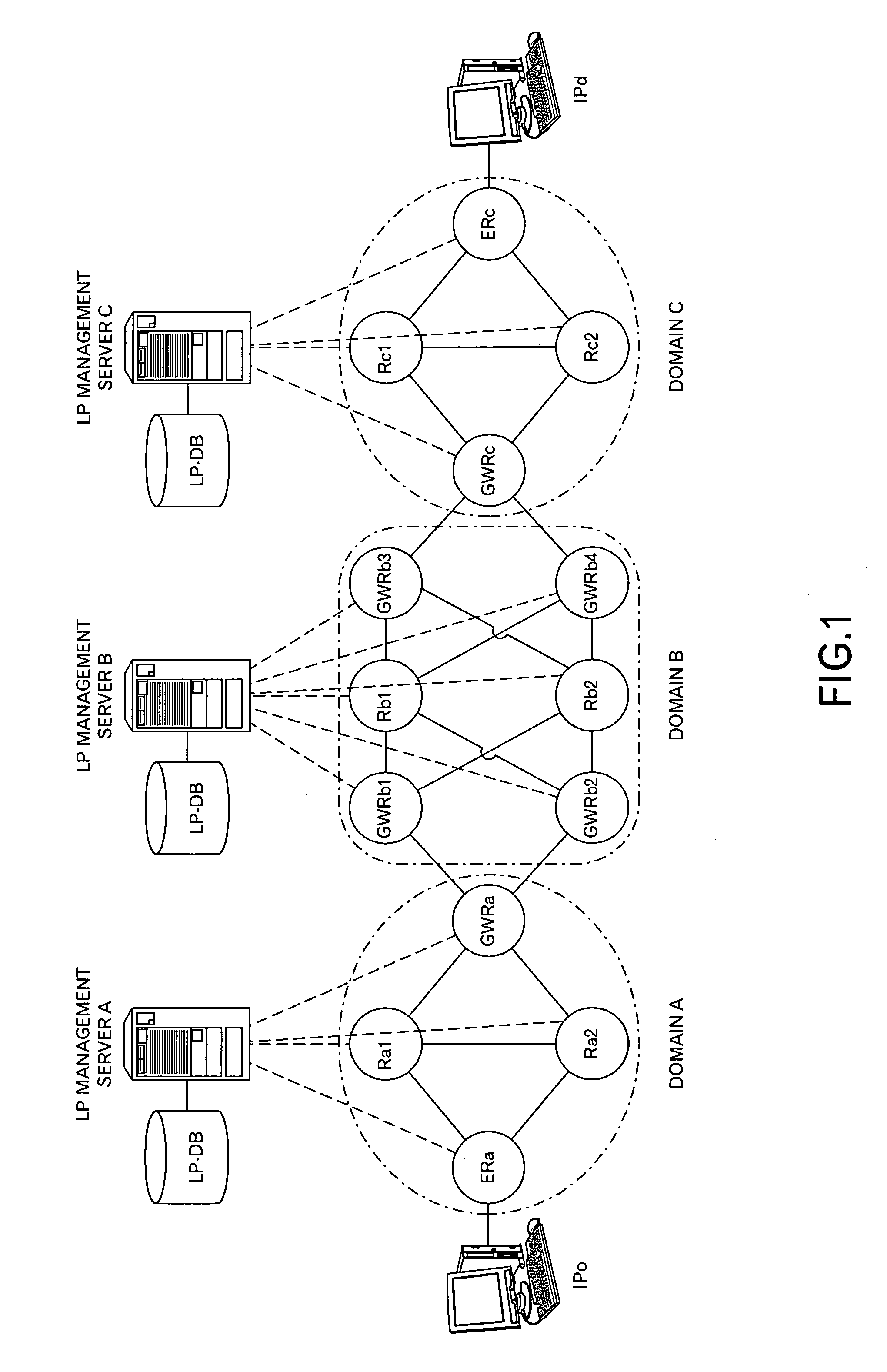
[0048]FIG. 1 shows a conceptual diagram of a network according to one embodiment of the invention. In this embodiment, an LP management server A is connected to a domain A including routers, such as a node ERa (Edge Router), nodes Ra1 and Ra2, and a node GWRa (Gateway Router). An LP management server B is connected to a domain B including routers, such as nodes Rb1 and Rb2 and nodes GWRb1, GWRb2, GWRb3, and GWRb4. An LP management server C is connected to a domain C including routers, such as a node ERc, nodes Rc1 and Rc2, and a node GWRc. In addition, the node GWRa is connected to the nodes GWRb1 and GWRb2, and the node GWRc is connected to the nodes GWRb3 and GWRb4. Incidentally, a router having a link to a computer having a source address IPo (a group of IP addresses in a predetermined sub-network) or the like and a router having a link to a computer having a destination address IPd (a group of IP addresses in a predetermined sub-network) or the like are denoted as edge routers E...


PUM


Abstract

This invention is to enable inter-domain routing using MPLS. When communication is carried out passing through plural domains, respective management servers managing respective domains cooperate to carry out path constitution and optimum routing. At the path constitution, the respective management servers connect links within the respective controlling domain to constitute paths to reach a target address. When the paths are constituted, label data is notified to nodes associated with the constituted paths, and isused at the routing. At the routing, the management server controlling the source domain obtains the dynamic transmission bandwidths from the respective management servers, and identifies the routing policy from a port number of a request to be routed or the like to identify the optimum path. When the optimum path is determined, it is possible to carry out the routing using the label data held in the respective nodes.

Description

TECHNICAL FIELD OF THE INVENTION [0001] The present invention relates to a path control technique for a network. BACKGROUND OF THE INVENTION [0002] A conventional path control technique for a network has following problems: (a) it is impossible to detect routes being congested, in advance; (b) symmetric routing in uplink and downlink cannot be forcibly carried out; (c) it is impossible to reflect the state of a server in routing; (d) it requires a load and / or time to check the states of routes; and (e) it requires a load and / or time to carry out a dynamic processing. Especially, because the Internet, which has come into wide use in recent years, has developed without considering the entire efficiency improvement, it has a lot of problems in efficiency. For example, as for the routing and switching, because autonomous operations are assumed, the protocol is complicated, and there are a lot of case in which the state in the network is not unknown. [0003] In order to solve these proble...

Claims


Application Information

Patent Timeline
Patent Type & Authority Applications(United States)
IPC IPC(8): H04L12/56H04L12/66H04L12/701H04L12/715
CPCH04L45/04H04L45/00H04L45/50
Inventor SHIMIZU, TAKAOTAKAHASHI, NAOYUKIMATSUKAWA, NORIKAZUIITSUKA, KAZUHIROKITADE, MICHIO
Owner FUJITSU LTD
Why Eureka
Try Eureka