
Co-existing static and dynamic IP multicast

a static and dynamic ip multicast and co-existing technology, applied in the field of ip multicasting, can solve the problems of inability to provide channel surfing

Inactive Publication Date: 2006-11-23
RPX CORP
View PDF11 Cites 78 Cited by
  • Summary
  • Abstract
  • Description
  • Claims
  • Application Information

AI Technical Summary

Benefits of technology

[0016] The methods and apparatus of the present invention allow both dynamic and static IP multicast to coexist and allow the states created by both multicast methods to be maintained independently. By providing a range of Class D IP addresses which is defined and reserved for static IP multicast, network routers can distinguish static multicast groups from dynamic multicast groups and can apply a new rule set to PIM JOIN / PRUNE and IGMP JOIN / LEAVE messages. Static channels can thereby be added or removed at the routers without triggering any dynamic multicast. The methods and the apparatus of the invention may find particular use in TV broadcasting, where commonly accessed TV channels may be configured using static multicast while less commonly accessed TV channels or specialty channels (such as pay-per-view channels) may be configured using dynamic multicast.

Problems solved by technology

However, in applications in which hosts leave and join groups frequently, users may experience undesirable delay as RPTs and SPTs are established, torn down, or altered.
This consumes processing power at the routers, and more importantly (for the customer) can result in unacceptable delay in channel surfing because the PIM-SMM messages are transmitted around the network to tear down the old multicast tree and rebuild a new one.
However, static multicast lacks the flexibility offered by dynamic multicast in automatic creation and maintenance of SPT trees as groups are added.

Method used


Image

  • Co-existing static and dynamic IP multicast
  • Co-existing static and dynamic IP multicast
  • Co-existing static and dynamic IP multicast

Examples


Embodiment Construction

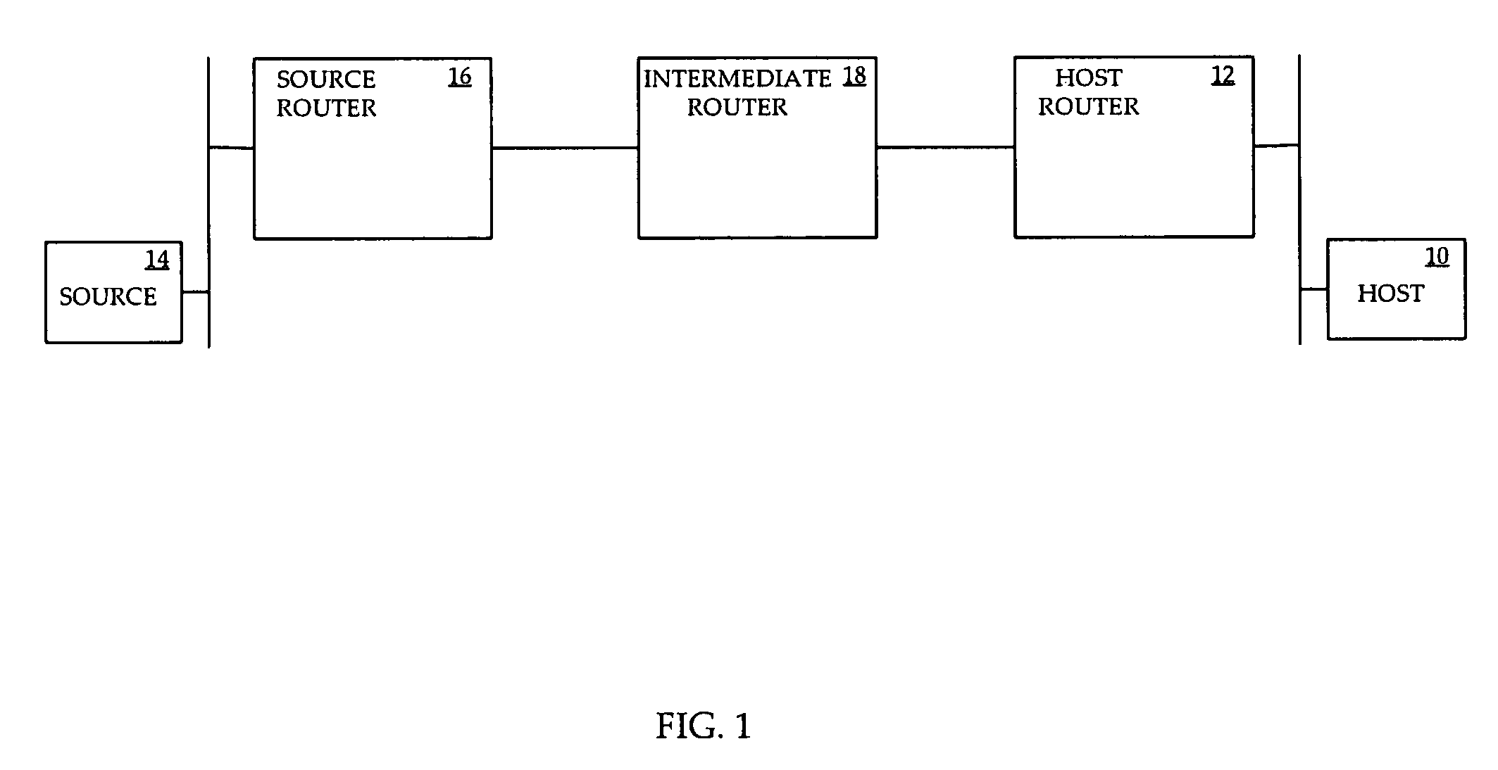
[0024] Referring to FIG. 1, a block diagram of a portion of an example communication network is shown. A host 10, operated by a user, is connected to the network through a host router 12. The host 10 may be any device capable of requesting and receiving IP multicast traffic, such as a set top box (STB). A multicast source 14 is connected to the network through a source router 16, and offers IP multicast content for multicast group G1. The host router 12 and the source router 16 communicate through an intermediate router 18. The layout of FIG. 1 is for example purposes only, and more generally there may be a plurality of hosts, a plurality of host routers, a plurality of sources, a plurality of source routers, and a plurality of intermediate routers between host routers and source routers. The source typically offers content in more than one multicast group.

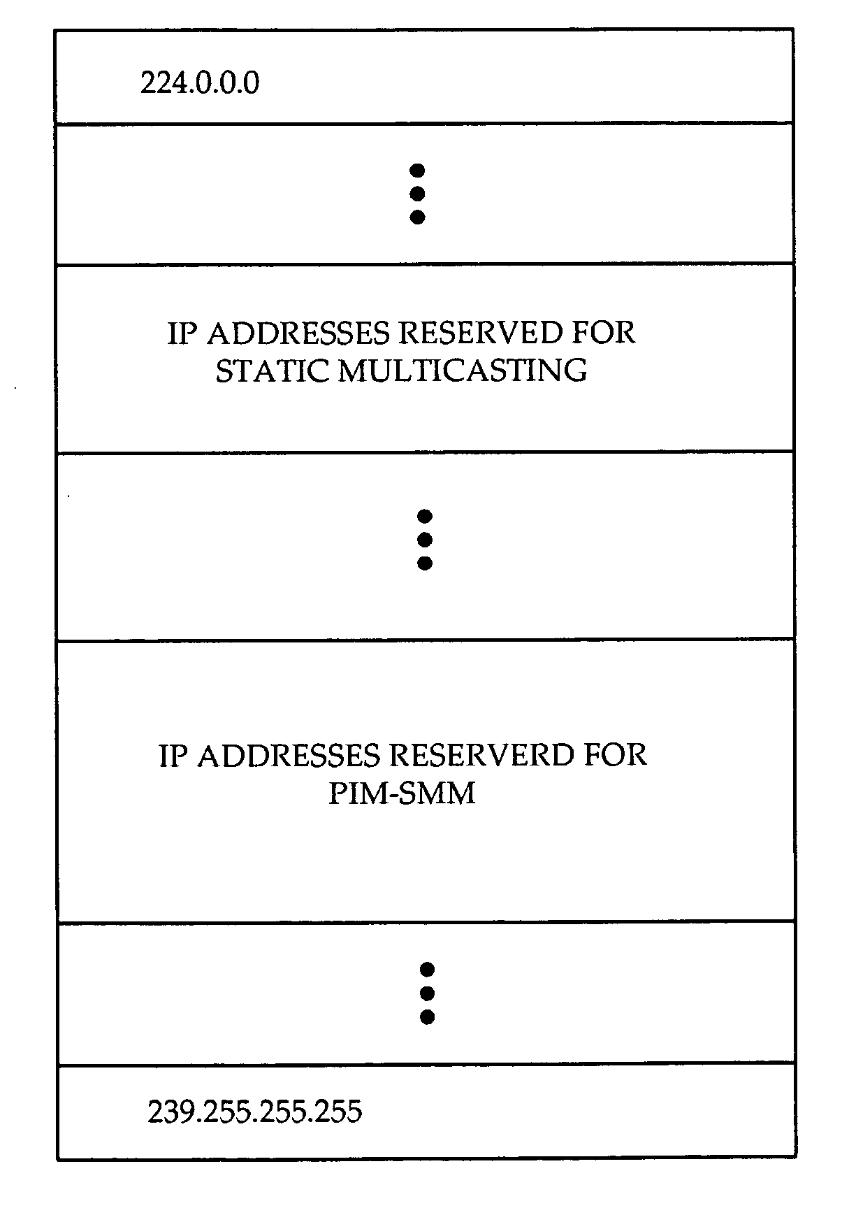
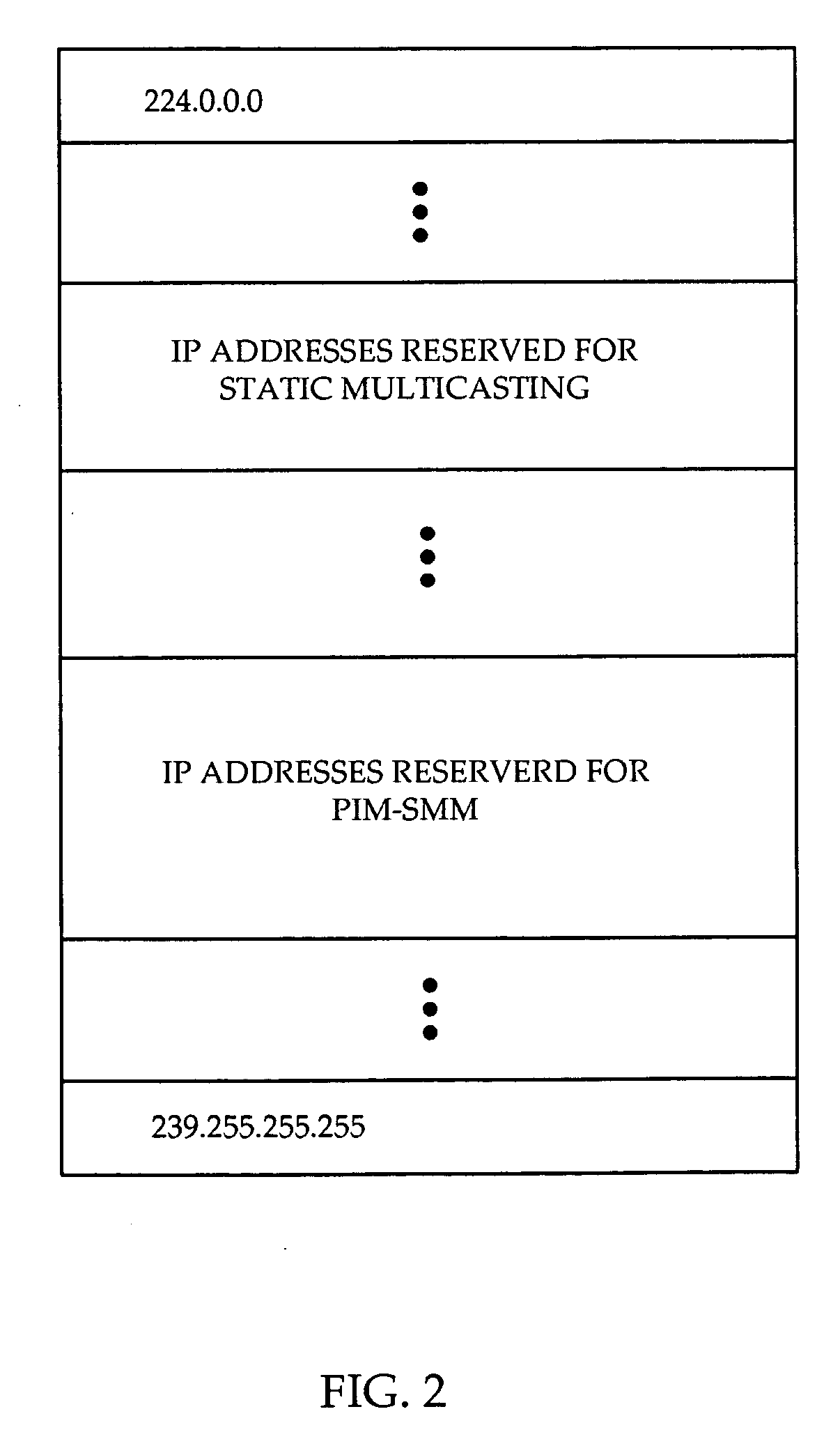
[0025] Referring to FIG. 2, a diagram of Class D IP addresses is shown. Class D IP addresses are reserved for IP multicasting, ...


PUM


Abstract

A system and method are provided for providing both static and dynamic IP multicasting. The concept of a multicast Static-Range is introduced which allows the coexistence of static and dynamic IP multicast. The multicast Static-Range is a set of Class D IP addresses which is reserved for static multicasting, and is configured at all routers. When a router receives a PIM message or an IGMP message, the router determines whether the group specified in the message is within the multicast Static-Range. If the group pertains to a static multicasting group, the router does not propagate the message to upstream routers using PIM-SM or PIM-SSM protocols, and only connects or disconnects interfaces internal to the router. If the multicast group address in the message is not within the multicast Static-Range, the router recognizes that the message pertains to a dynamic multicasting group and implements PIM or IGMP protocols as usual. If the invention is used for broadcasting TV, the low end of TB channels or commonly used channels can be created as static IP multicast. This way, a user can access or leave such channels without an entire shortest path tree being created or torn down, improving access time and channel surfing for a user. Also, pay-per-view, digital or less frequently used channels can be created using dynamic IP multicast with traditional PIM-SSM protocol, in order to make efficient use of router resources.

Description

FIELD OF THE INVENTION [0001] The invention relates to IP multicasting in communication networks, and more particularly to IP address ranges for use in creation of IP multicast distribution trees. BACKGROUND OF THE INVENTION [0002] To establish a multicast tree from a source which provides multicast content to several hosts which desire to receive the traffic, two general approaches are Dynamic IP Multicast and Static IP Multicast. In dynamic multicast, a multicast protocol such as Protocol Independent Multicast-Sparse Mode (PIM-SM) or Protocol Independent Multicast-Source Specific Mode (PIM-SMM) is used to create and propagate the multicast tree from multicast hosts to a multicast source. In static multicast, the multicast protocol is not responsible for establishing and propagating the multicast tree. Rather, establishment of the multicast tree is effected by other means such as network management or through configuration. [0003] In PIM-SM, a shortest path tree (SPT) can not be es...

Claims


Application Information

Patent Timeline
IPC IPC(8): H04L12/56H04J3/26
CPCH04L12/185H04L29/12292H04L61/2069H04L45/16H04L45/48H04L45/02H04L61/5069H04L45/484H04W4/08H04L12/28
Inventor ROKUI, REZA MOHAMMAD
Owner RPX CORP
Learn More