Image encoding apparatus and method, computer program, and computer-readable storage medium

a technology of image data and encoding method, applied in the field of encoding image data, can solve the problems of insufficient method of efficiently encoding data while switching encoding techniques and using them, and achieve the effect of efficient coding data

Inactive Publication Date: 2006-11-23
CANON KK
View PDF35 Cites 20 Cited by
  • Summary
  • Abstract
  • Description
  • Claims
  • Application Information

AI Technical Summary

Benefits of technology

[0018] The present invention has been made in consideration of the above situation, and has as its object to provide a technique of efficiently coding data when encoding is executed selectively using encoding of each pixel and run-length coding.

Problems solved by technology

However, a method of efficiently encoding data while these encoding techniques are switched and used has not been established.

Method used


Image

  • Image encoding apparatus and method, computer program, and computer-readable storage medium
  • Image encoding apparatus and method, computer program, and computer-readable storage medium
  • Image encoding apparatus and method, computer program, and computer-readable storage medium

Examples


first embodiment

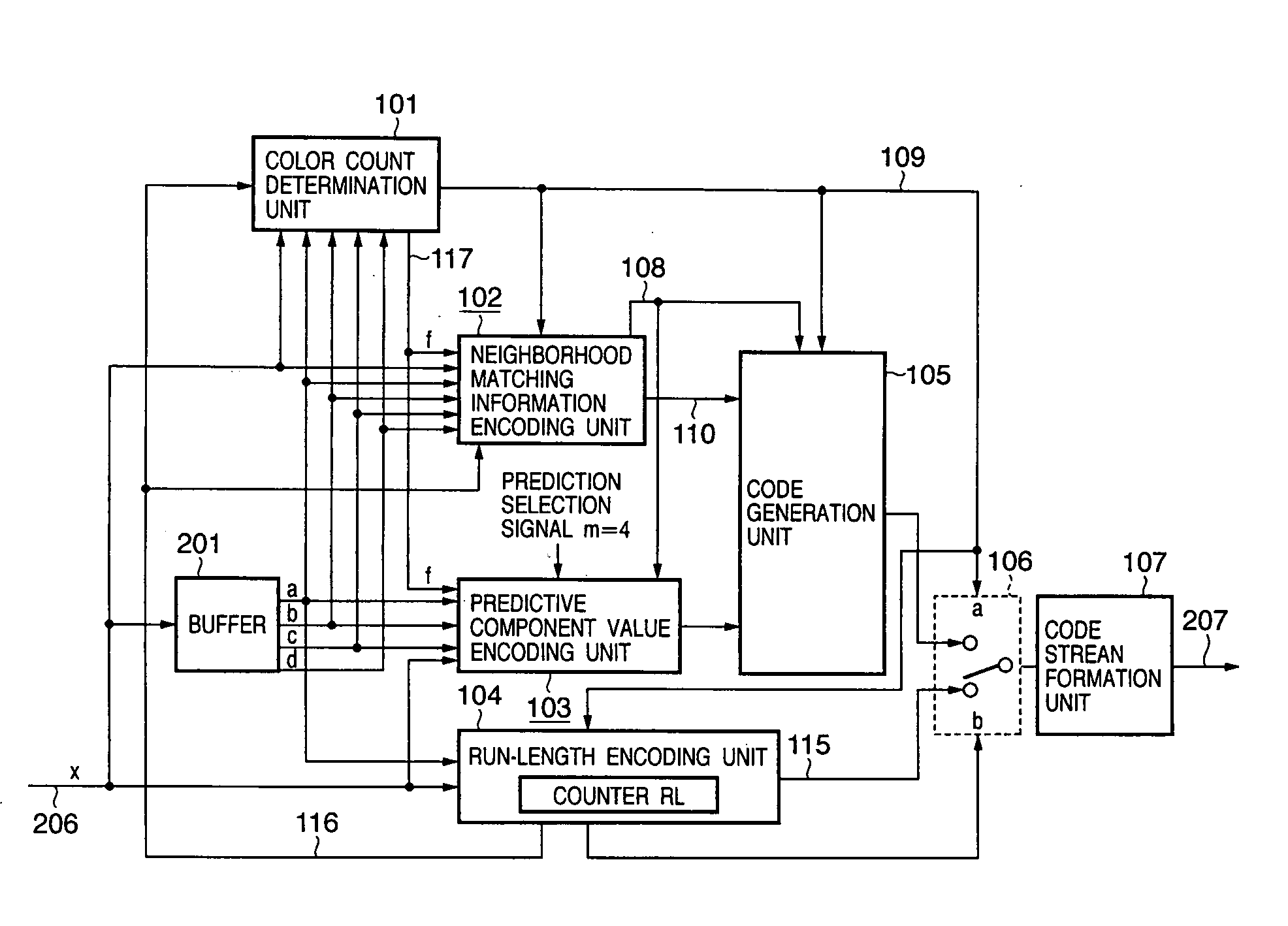
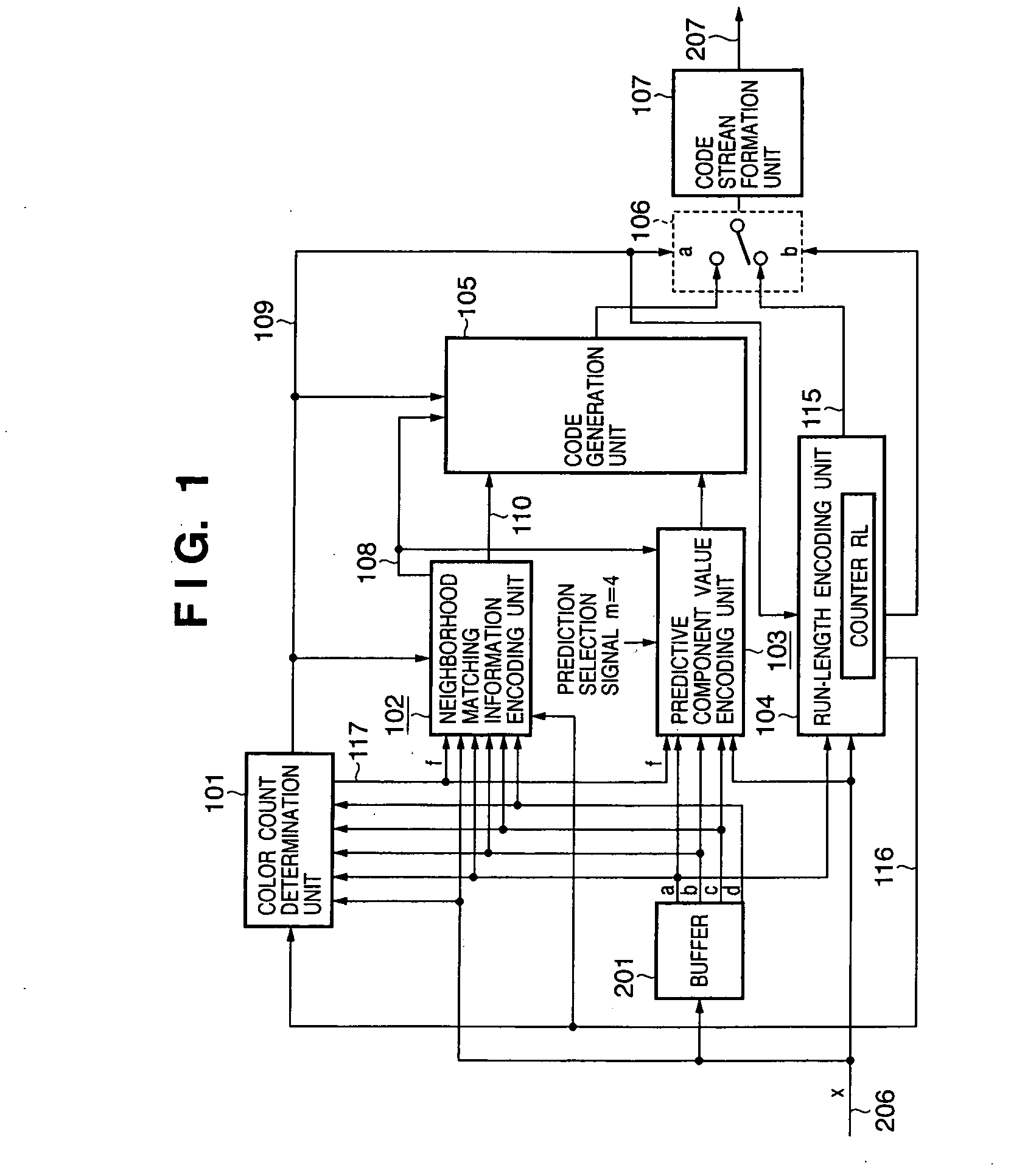
[0055]FIG. 1 is a block diagram showing an image encoding apparatus according to the first embodiment. As shown in FIG. 1, the image processing apparatus according to the first embodiment comprises a color count determination unit 101, neighborhood matching information encoding unit 102, predictive component value encoding unit 103, run-length encoding unit 104, code generation unit 105, switch 106, code stream formation unit 107, and buffer 201. In FIG. 1, reference numerals 108, 109, 110, 206, and 207 denote signal lines. The same reference numerals denote blocks which perform the same operations as those of the processing blocks of the conventional image processing apparatus, and a description thereof will be omitted. An image encoding process in the apparatus of FIG. 1 will be explained. In the first embodiment, the prediction selection signal m=4.

[0056] Image data to be encoded by the image processing apparatus according to the first embodiment is image data of R, G, and B col...

second embodiment

[0155] In the first embodiment, when the pixel X of interest ends the run and a predicted value for predictive encoding is obtained, “f”, “b”, and “c” are used by replacing the pixel “a” in the reference pixels “a”, “b”, and “c” with the reference pixel “f” which ends the run in previous run-length encoding. In the second embodiment, a plurality of colors of pixels which end runs before the pixel X of interest are stored as reference pixels “f”, and a pixel whose color appears frequently is referred to.

[0156] The second embodiment will explain an example of implementing this process by a computer program. The apparatus configuration is the same as that in FIG. 14.

[0157] Process procedures are shown in the flowchart of FIG. 19. The flowchart in FIG. 19 is different from that in FIG. 17 in that steps S1701 and S1702 in FIG. 17 are replaced with steps S1941 and S1942, a table which holds the component values and appearance frequency of an appearance color is allocated in a RAM 1402 p...

third embodiment

[0163] In the third embodiment, a pixel immediately before a pixel serving as the origin of the run is referred to as the reference pixel f, instead of a pixel which ends the run before the pixel X of interest. It is promised that Xf≠Xa and the position of Xf is much closer (at least within one line) to the pixel X of interest. The probability of X=Xf rises, and higher encoding efficiency can be expected.

[0164] It should be noted that run length-encoded data in the third embodiment is used to generate the code word of the “run” itself and pixel-encoded data (one of data in FIGS. 8A to BC) having a color at the origin of the run is always positioned immediately before the run length-encoded data, with one exception in which the pixel of interest is positioned at the start of each line of an image to be encoded.

[0165] In order to store a pixel immediately before a pixel serving as the origin of the run in performing run-length encoding, the process is executed in accordance with pro...


PUM


Abstract

Image data is efficiently encoded using a predict coding unit and a run-length coding unit. The predict coding unit encodes a target pixel X on the basis of difference between the value of the target pixel and a predict value calculated from pixels neighboring the target pixel. The run-length coding unit starts the measuring the run when the number of colors contained in four pixels “a”, “b”, “c”, and “d” near the target pixel X is 1, and outputs encoded data of the run when the target pixel is different from an immediately preceding pixel “a”. Then, the predict coding unit starts the encoding. At this time, since the target pixel is different from the preceding pixel, the preceding pixel is excluded from references for generating the predict value. Instead of the preceding pixel, an pixel, which has been encoded, satisfying a specific condition is referred to.

Description

FIELD OF THE INVENTION [0001] The present invention relates to a technique of encoding image data. BACKGROUND OF THE INVENTION [0002] As a conventional image coding method, a predictive encoding-based method has been proposed. The predictive coding method comprises a sequence conversion unit which converts image data into a prediction error by predictive transform, and an entropy encoding unit which converts the prediction error output from the sequence conversion unit into encoded data of less redundancy. [0003] As an example of a scheme using predictive encoding, an international standard JPEG-LS (ITU-T T.87|ISO / IEC 14495-1) is known. [0004] JPEG (ITU-T T.81|ISO / IEC 10918-1) defines a lossless coding scheme in which an independent function is based on predictive coding. This lossless coding scheme will be called a JPEG lossless coding mode. In the JPEG lossless coding mode, seven prediction equations are defined as a method of predicting the value of a pixel of interest (target pi...

Claims


Application Information

Patent Timeline
Patent Type & Authority Applications(United States)
IPC IPC(8): G06K9/36H04N1/419H04N19/00H04N19/593H04N19/90H04N19/91H04N19/93
CPCH04N19/93H04N19/593G06T9/00G06V10/20
Inventor MATSUMOTO, YUKIKAJIWARA, HIROSHI
Owner CANON KK
Why Eureka
Try Eureka