Air fan

a technology of air fans and fans, which is applied in the field of air fans, can solve the problems of affecting the operation the air temperature the air quality of the air conditioner, so as to facilitate the oscillation of the head, avoid the effect of prone to overturning and safe air fast speed

Inactive Publication Date: 2006-11-23
NGAN HON HING
View PDF15 Cites 18 Cited by
  • Summary
  • Abstract
  • Description
  • Claims
  • Application Information

AI Technical Summary

Benefits of technology

[0022] As compared with the prior art, the present invention is advantageous in the following points: 1) the rotation inertia of the oscillating member (i.e., the wind guard plate and the wind reject plate) is smaller, so the air fan according to the present invention is enemy saving; besides, no space need to be reserved to facilitate oscillation of head of the air fan, which is particularly advantageous in a narrow environment; 2) the enclosure is stationary and encloses the oscillating wind guide device so that the air fast is pretty much safer; 3) the internal oscillation technology allows the center of gravity of the whole air fan to be stable and steady so that the center of gravity is not shifted any more as in the conventional fans due to oscillation of head, As a result, the air fan according to the present invention is extremely stable and is not liable to overturn.

Problems solved by technology

In addition, the conventional fans with oscillating heads require a predetermined indoor laze for oscillation of the head, which is particularly disadvantageous in a narrow environment.
To sum up, one defect of the fans in the prior art is greater consumption of energy and larger occupation of space.
As the oscillating part (the whole fan head and the whole substantially cylindrical housing) or rotating part (guide vanes) for changing wind direction are exposed to the outside in the prior art, oscillation or rotation might injure by accident the ambient object or human beings such as an operator.
For example, when a juvenile operates the air fan, the oscillating head, housing or rotating varies might injure his fingers by accident.
In summary, another defect of fans in the prior art is a certain of danger in operation.
In addition, the conventional fan with oscillating head, in operation, may shift its center of gravity due to oscillation of the head.
Therefore, another defect of fans in the prior art is that the fan in operation is not stable and steady enough and is liable to overturn.

Method used


Image

  • Air fan
  • Air fan
  • Air fan

Examples


Embodiment Construction

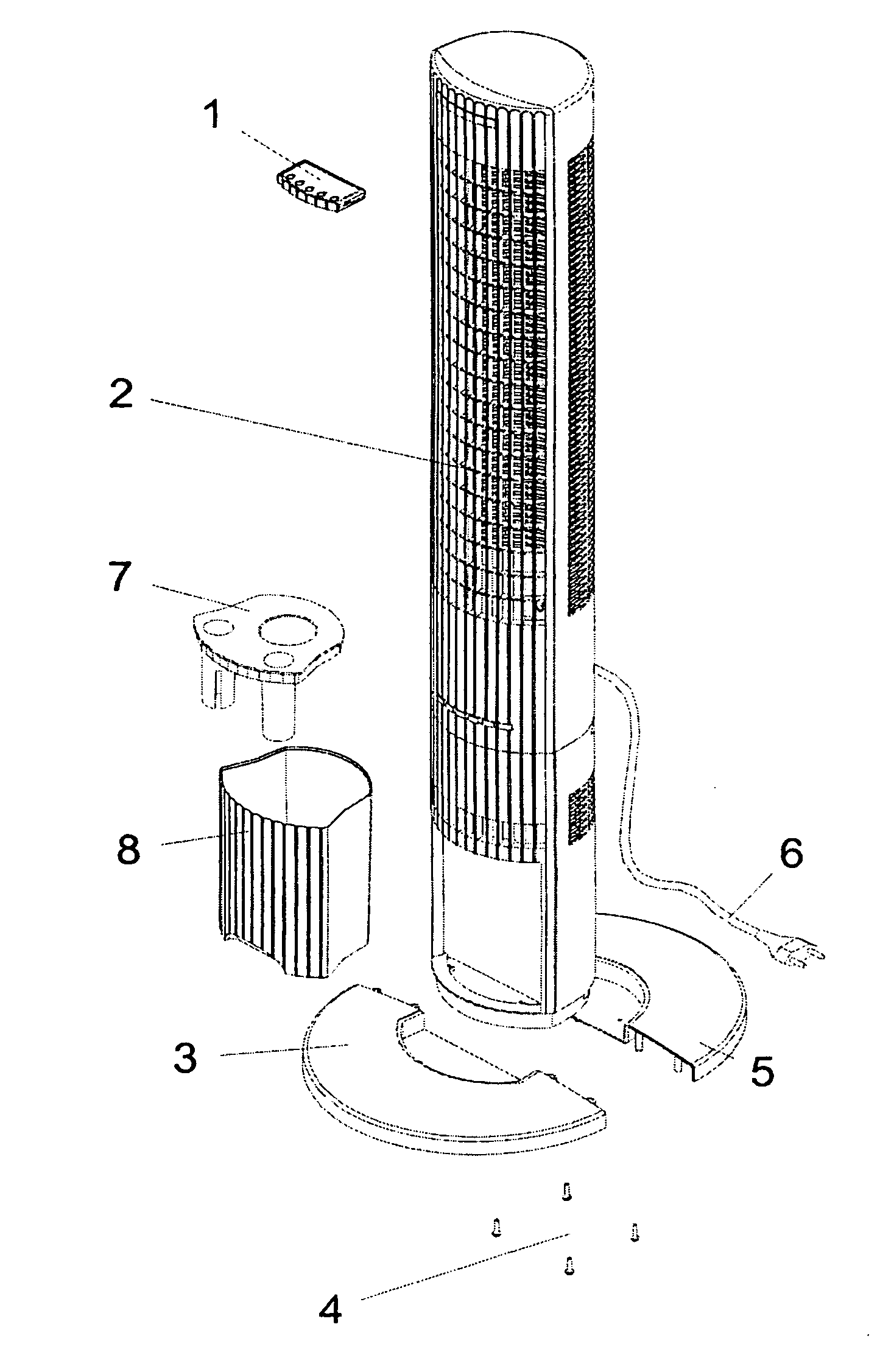
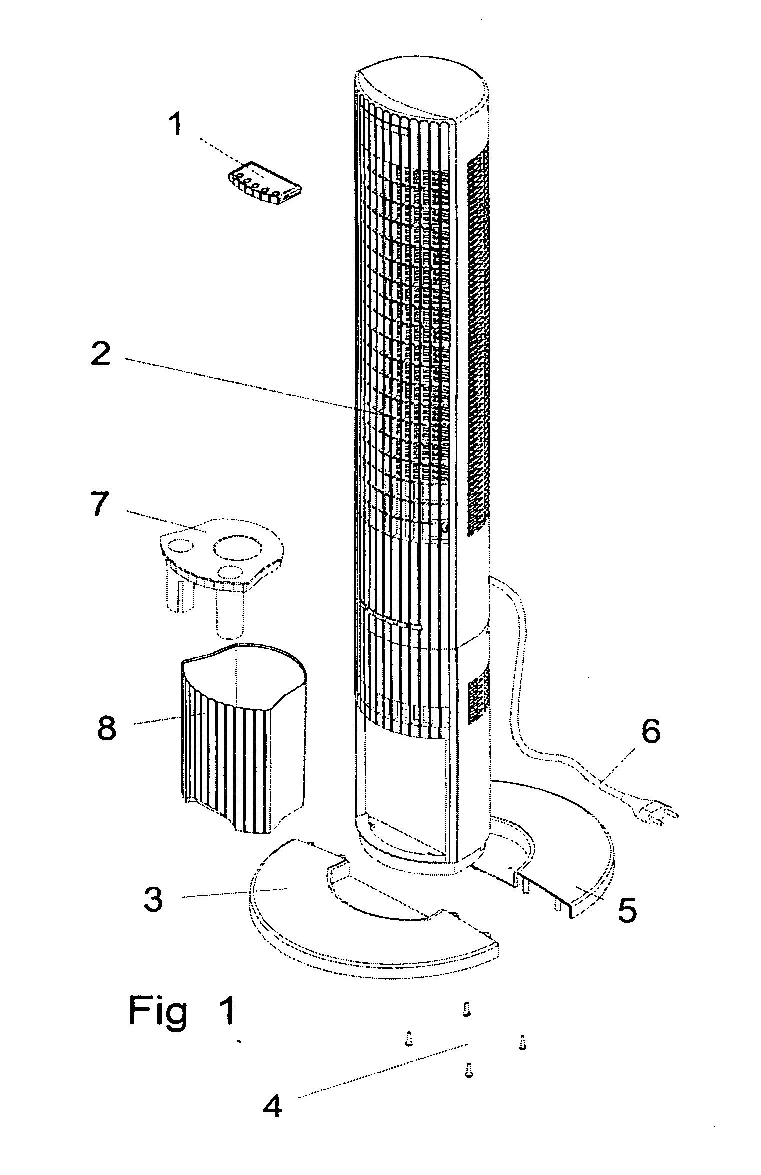
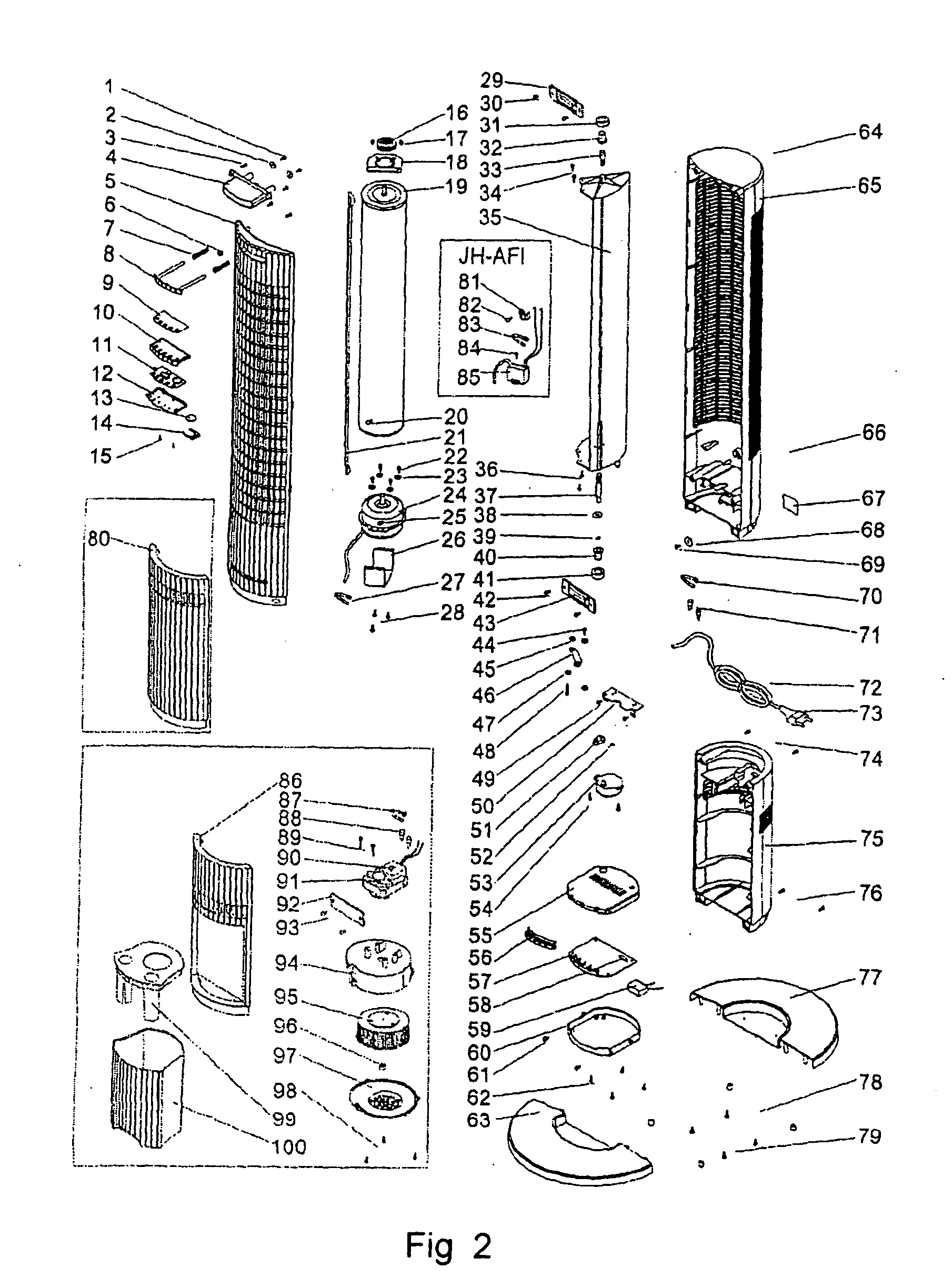
[0033] As shown in FIGS. 1 and 2, the air fan of the preferred embodiment (the applicant's product model JH-AFN) according to the one aspect of the present invention comprises a substantially cylindrical main propeller 19 which may be a conventional propeller used in a transverse flow fan or of other similar configurations, so the specific structure of the main propeller is not described in detail herein. In the description hereunder, “axial direction” refer to the direction of the vertical axis of the main propeller 19 when the air fan is placed normally, and “radial direction” refers to the direction perpendicular to the axis. A main motor 24 is operatively connected to the main propeller 19 in a convectional manner along the axial direction of the main propeller 19, and is used to drive the main propeller 19 to rotate to generate air stream. The main motor 24 is detachably held in a main motor holder 26 via screws.

[0034] The air fan according to the present invention further com...


PUM


Abstract

The present invention provides air fans with enhanced oscillating mechanism. In one aspect of this invention, the air fan comprises main propeller (19), a main motor (24) operably connected to the main propeller (19), driving the main propeller (19) to rotate to generate air stream, and a wind guide device composed of a wind guard plate (35) and a wind reject plate (21) and surrounding the main propeller (19). An auxiliary motor (53) operably connected to the wind guide device via a rotation-oscillation shifting device, for driving the wind guide device to oscillate to change the wind direction. In a further aspect of this invention, only the motor for the oscillating mechanism is in motion to drive the relatively lighter wind channel while the enclosure and motor for the wind wheel remain static during operation. The air fans feature less safety hazard, a prolonged service life, a lower noise and easier operation.

Description

CROSS REFERENCE TO RELATED APPLICATIONS [0001] This application is a continuation-in-part of U.S. patent application Ser. No. 11 / 101,875, filed on Apr. 7, 2005, the entire content of which is incorporated here by reference.TECHNICAL FIELD [0002] The present invention relates to air fans, and especially relates to air fans with enhanced oscillating mechanisms. BACKGROUND ART [0003] The prior art discloses various fans such as ground fans, table fans, ceiling fans, vane rotating fans, and transverse flow type fans, some examples of which can be seen in the patent documents U.S. Pat. No. 6,344,065B1, CN1063530C, CN10343A and CN1141603A or in FS29-SW V4 tower fan as shown in FIG. 4. [0004] As for conventional ground fans, table fans, ceiling fans and transverse flow type fans, wind direction is changed by allowing the whole fan head and the whole substantially cylindrical housing to oscillate. In this circumstance, the whole fan head and the whole substantially cylindrical housing have ...

Claims


Application Information

Patent Timeline
Patent Type & Authority Applications(United States)
IPC IPC(8): F24F7/00
CPCF04D17/04F24F2221/00F24F7/007F04D25/10
Inventor NGAN, HON HING
Owner NGAN HON HING
Why Eureka
Try Eureka