
Surgical jig

a surgical and jig technology, applied in the field of surgical jigs, can solve the problems of difficulty in shoe fitting, weight to be transferred to the second and third metatarsal heads, and difficulty in making cuts in the desired plan

Inactive Publication Date: 2006-11-23
MURRAY BROWN JAMES HAMILTON
View PDF16 Cites 75 Cited by
  • Summary
  • Abstract
  • Description
  • Claims
  • Application Information

AI Technical Summary

Benefits of technology

[0011] It is a further advantage of the invention that a surgeon is able to guide a longitudinal cut of the first metatarsal with a jig that refers to the plantar aspect of the foot, so that the resulting cut is in a known and reproducible plane.
[0012] Preferably the cutting guide includes a planar surface disposed at an angle to the reference surface.
[0013] Preferably the reference surface is the upper surface of a base plate and the cutting guide is rigidly connected to the base plate.
[0014] Preferably an angled spacer is provided for increasing the angle between the planar surface and the reference surface, the spacer being attached to the upper surface of, the base plate, and the upper surface of the spacer becoming the reference surface.
[0015] Preferably end stops are provided at one or both ends of the planar surface.
[0016] Preferably the end stops are provided at a predetermined angle relative to a longitudinal axis of the cutting guide.

Problems solved by technology

The usual articulation between the first. metatarsal head and the two sesamoid bones beneath it is disturbed, typically causing pain as weight is put onto the foot.
In addition the first metatarsal head can become displaced dorsally, typically causing weight to be transferred to the second and third metatarsal heads when walking or standing, which can be painful.
Finally, the forefoot is broad which causes difficulty with shoe fitting.
The cuts are usually made with oscillating or reciprocating saw blades, and the surgeon may find it difficult to make the cuts in the desired planes in accordance with a pre-operative plan.

Method used


Image

  • Surgical jig
  • Surgical jig
  • Surgical jig

Examples


first embodiment

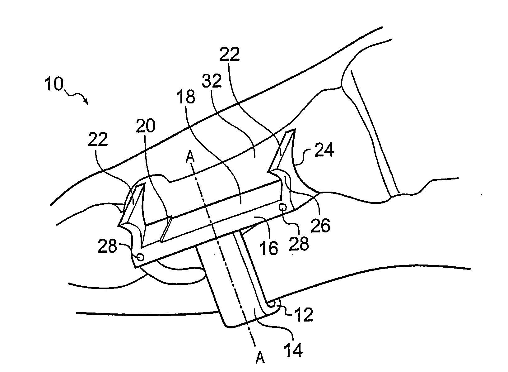
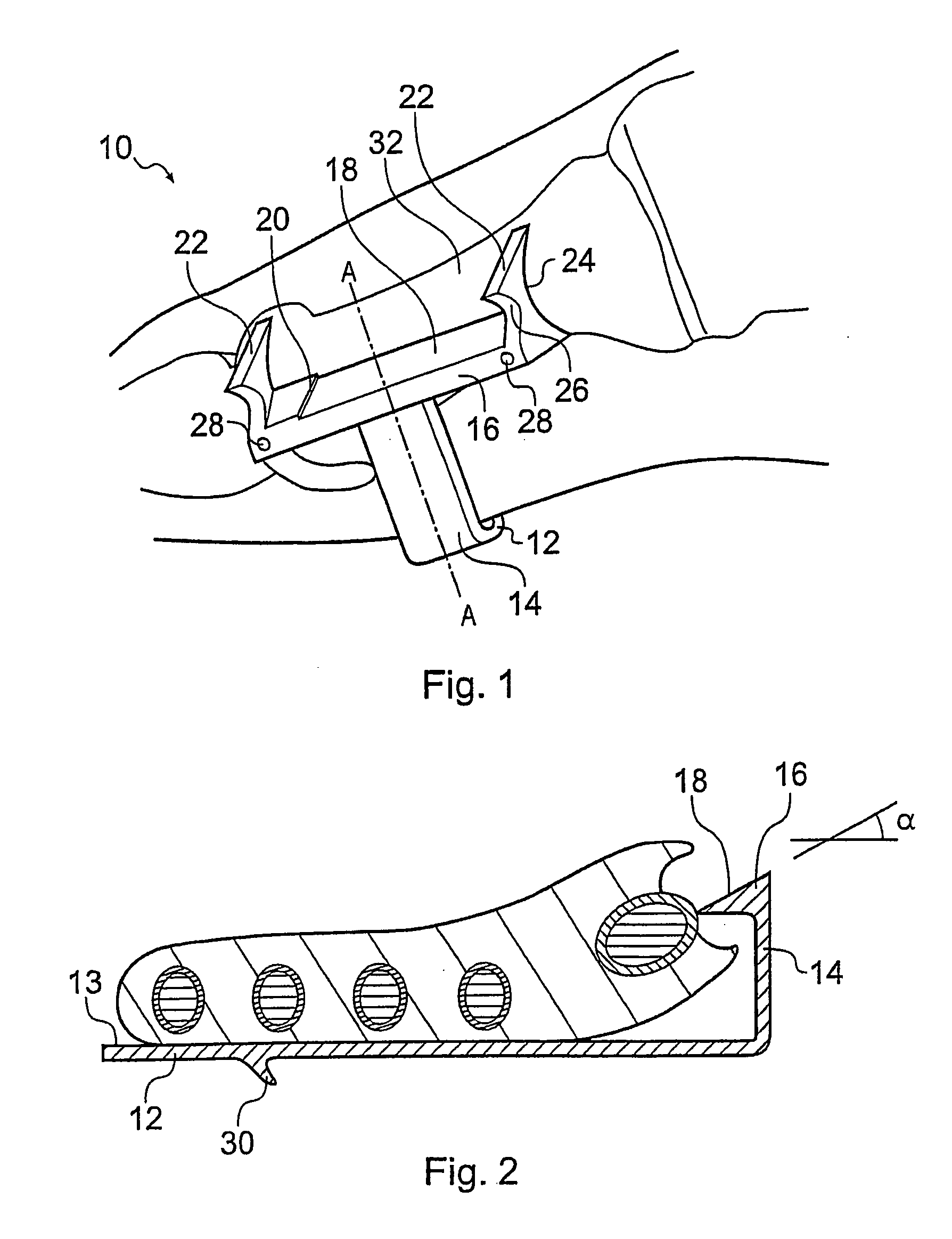
[0044] Referring firstly to FIGS. 1 and 2, a surgical jig is indicated generally at 10. The jig 10 comprises a base plate 12 having an upper reference surface 13, an arm 14 extending substantially perpendicularly from one end of the base plate 12, and a cutting guide or cutting block 16 mounted to the end of the arm 14. The arm 14 and base plate 12 are integrally formed.

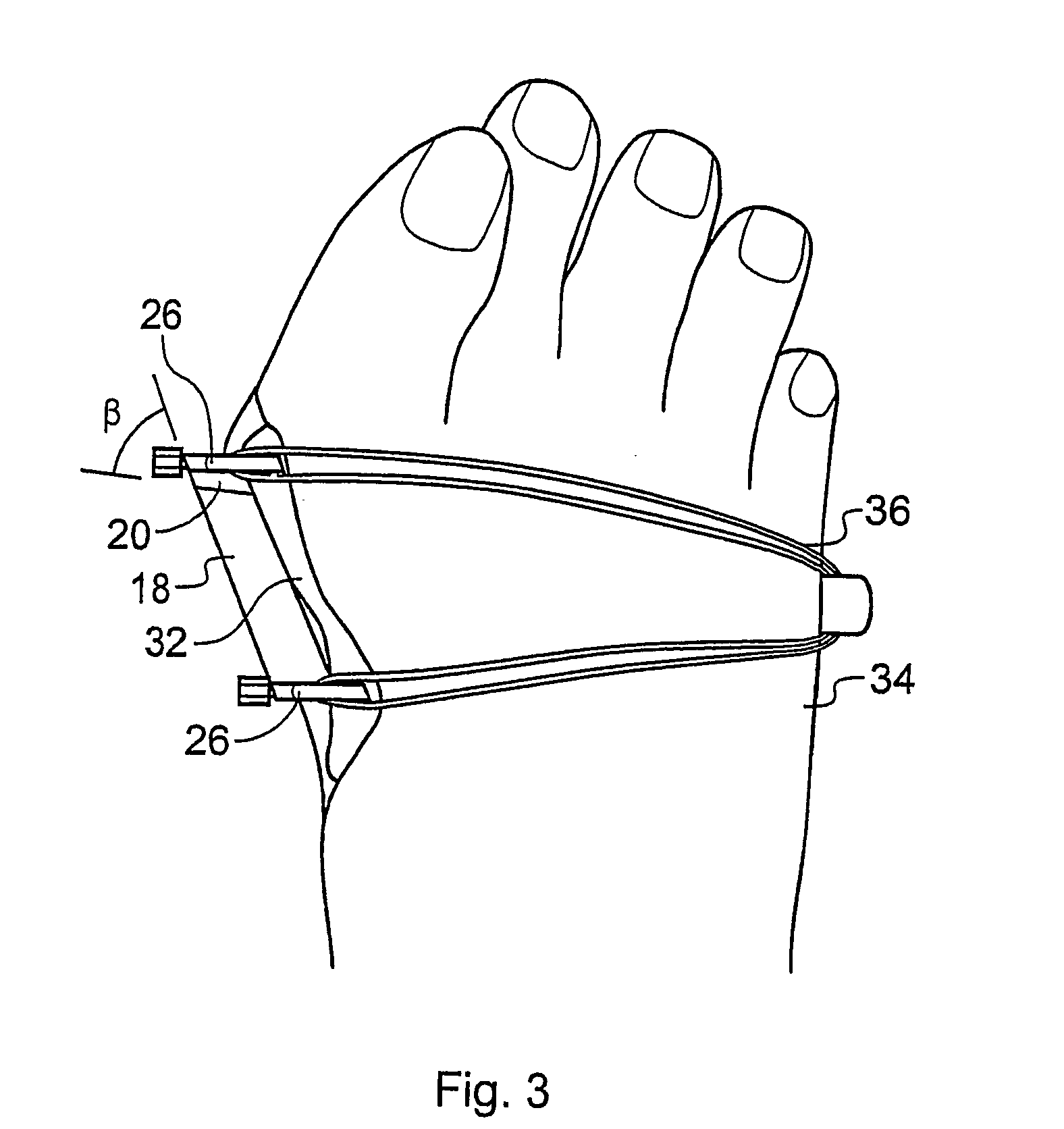
[0045] The cutting guide 16 has a planar surface 18 disposed at an angle a relative to the reference surface 13 of the base plate 12, as indicated in FIG. 2. End stops 20, one of which is shown in FIG. 1, may be provided at each end of the planar surface 18, which limit the movement of a cutting implement moving along the planar surface. The end stops are provided at an angle 0, see FIG. 3, relative to the longitudinal axis of the cutting guide.

[0046] An appendage in the form of an abutment 22 extends from each end of the cutting guide 16 and is profiled on its edge with a substantially semi-circular recess 24, whic...

second embodiment

[0052] the invention will now be described with reference to FIG. 5 of the drawings. In this embodiment, the surgical jig 110 also comprises a base plate 112 having an upper reference surface 113, an arm 114 extending substantially perpendicularly from one end of the base plate 112, and a cutting guide or cutting block 116 mounted to the end of the arm 114.

[0053] The cutting guide 116 has a planar surface 118 disposed at an angle a relative to the reference surface 113 of the base plate 112. An appendage in the form of an abutment 122 extends from each end of the cutting guide 116 and is profiled on its edge with a substantially semi-circular recess 124, which, as in the first embodiment, is shaped to fit against an exposed metatarsal bone. The other side of the abutment is provided with hooks or lips 126. An aperture 128 is provided through each end of the cutting guide 116, through which a pin or wire can be passed in order to secure the cutting guide to the first metatarsal of th...


PUM


Abstract

A surgical jig for use in performing a scarf osteotomy on the first metatarsal of the forefoot includes a cutting guide that is adapted to guide a cutting implement relative to a reference surface that is adapted to be placed against the plantar aspect of a forefoot. The jig has guide surfaces for guiding both the longitudinal cut and the transverse cuts of the operation. The jig is selected from one in a set of jigs by an overlay template, through which an X-ray of the forefoot can be viewed.

Description

CROSS-REFERENCE TO RELATED APPLICATIONS [0001] This application is a continuation of International Application No. PCT / GB2004 / 004500, filed Oct. 25, 2004, which claims priority from U.K. Patent Application Nos. 0324932.3, filed Oct. 25, 2003 and 0328181.3, filed Dec. 5, 2003. The disclosures of all of these applications are incorporated herein by reference. BACKGROUND OF THE INVENTION [0002] The present invention relates to a surgical jig, and more particularly to a surgical jig for guiding a cutting implement when operating on the human forefoot. [0003] Hallux Valgus is a relatively common disorder of the forefoot in which the first metatarsal diverges from the second metatarsal at an angle greater than usual, typically in excess of 9 degrees and often up to 20 degrees or more. This angle is known as the intermetatarsal angle (IMA). The usual articulation between the first. metatarsal head and the two sesamoid bones beneath it is disturbed, typically causing pain as weight is put o...

Claims


Application Information

Patent Timeline
IPC IPC(8): A61B17/58A61B17/15A61B17/17
CPCA61B17/15A61B2017/1775A61B17/1732A61B17/1775
Inventor MURRAY-BROWN, JAMES HAMILTON
Owner MURRAY BROWN JAMES HAMILTON
Learn More