Manufacture method for inner-fin tube and manufacture device for the same

Active Publication Date: 2006-11-30
DENSO CORP
View PDF1 Cites 27 Cited by
  • Summary
  • Abstract
  • Description
  • Claims
  • Application Information

AI Technical Summary

Benefits of technology

[0009] In this case, the inner fin member and the tube member are continuously formed in parallel. The transfer direction of the inner fin member can be readi

Problems solved by technology

However, generally, the band-shaped plate material cannot be bent in the width direction thereof

Method used


Image

  • Manufacture method for inner-fin tube and manufacture device for the same
  • Manufacture method for inner-fin tube and manufacture device for the same
  • Manufacture method for inner-fin tube and manufacture device for the same

Examples


first embodiment

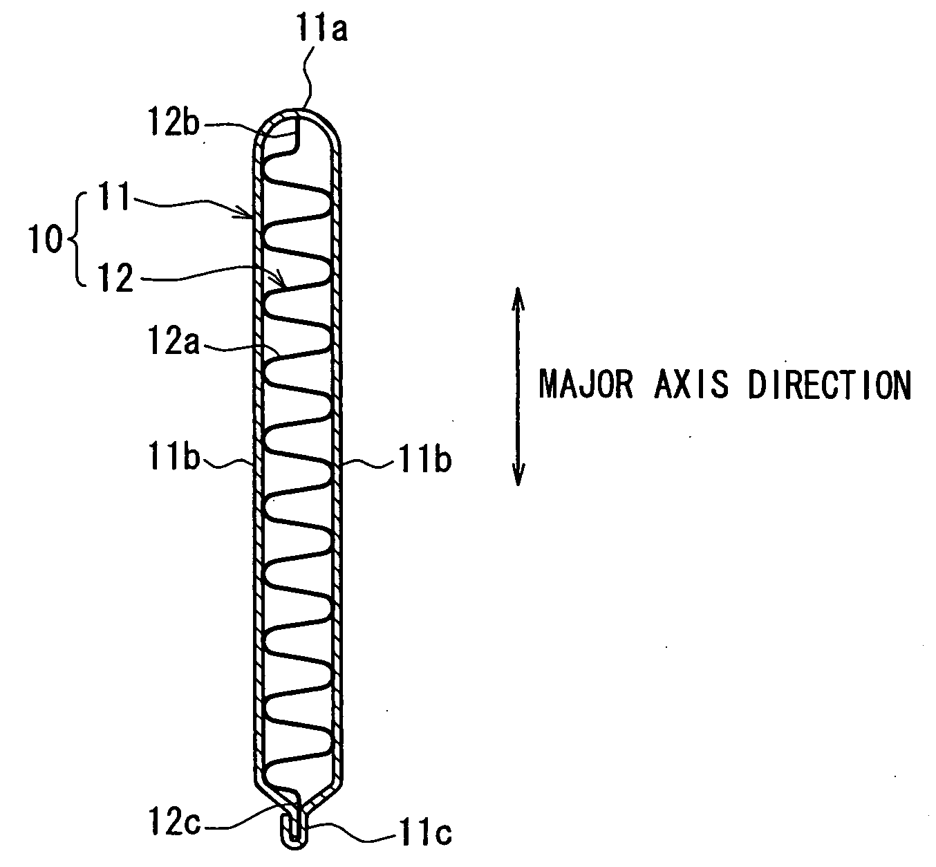
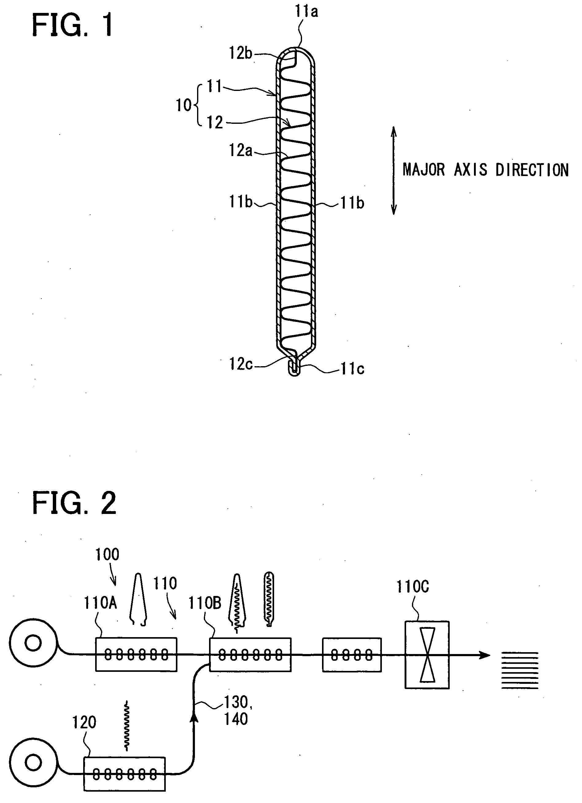
[0024] A manufacture device 100 for manufacturing an inner-fin tube 10 according to a first embodiment of the present invention will be described with reference to FIGS. 1-3. As shown in FIG. 1, the inner-fin tube 10 includes an inner fin member 12 and a tube member 11, in which the inner fin member 12 is arranged. The inner-fin tube 10 can be suitably used for a heat exchanger (heat-exchanging portion) of an evaporator or the like which is provided in a refrigerant cycle device, for example.

[0025] The tube member 11, being made of aluminum or the like, is constructed of a band-shaped thin plate material (first band-shaped plate material) which is bent to have a pipe shape, for example. The tube member 11 defines therein a passage with a flat-shaped cross section which is perpendicular to a longitudinal direction of the tube member 11. That is, this cross section of the tube member 11 has a thin-long shape.

[0026] The tube member 11 is provided with a bend portion 11a, two flat pla...

second embodiment

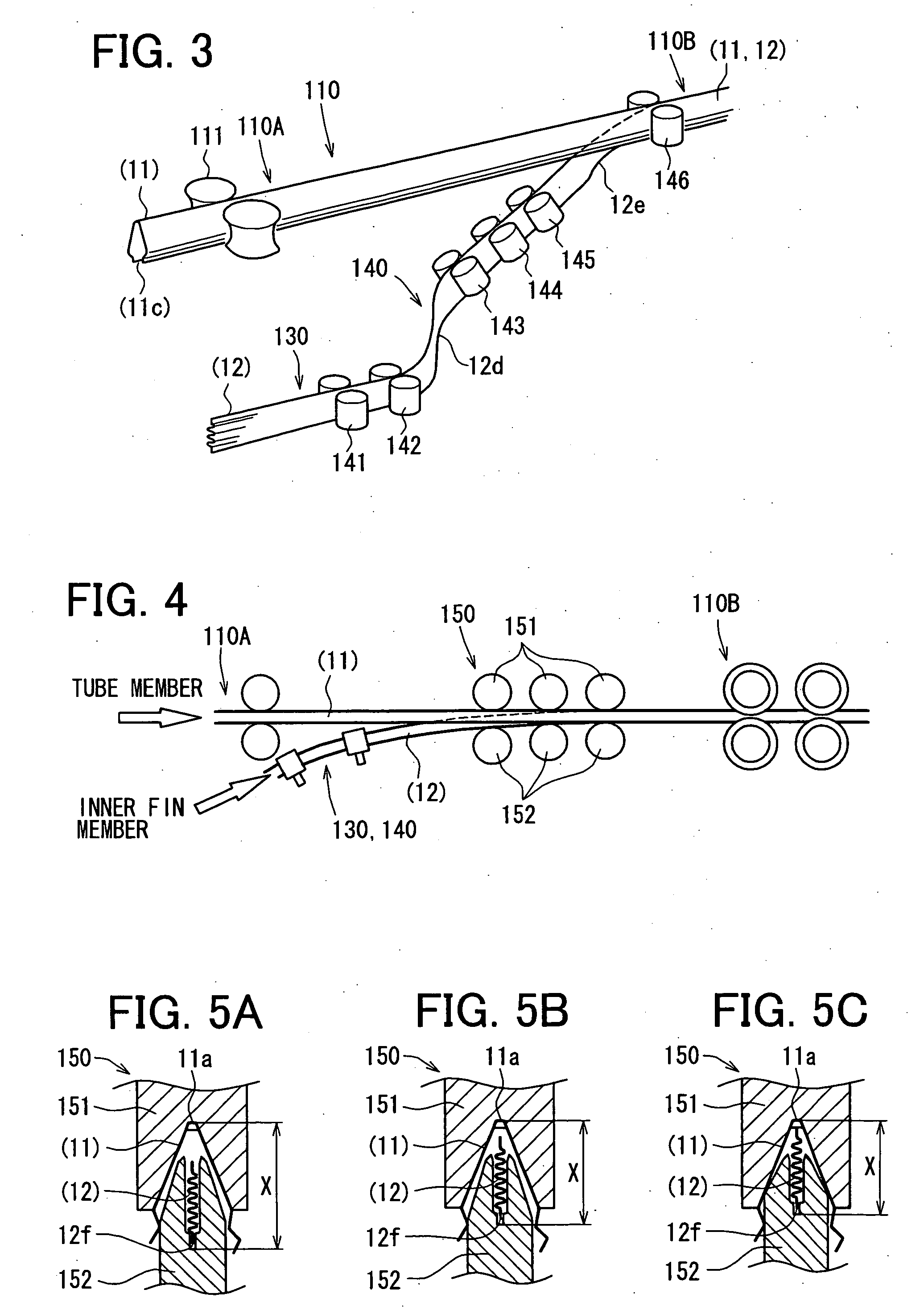
[0052] A second embodiment according to the present invention will be described with reference to FIGS. 4-5C. In this case, an inner fin shifting unit 150 is further arranged in front of the position where the inner fin member 12 is merged into the tube member 11 at the assembling / swaging portion 110B.

[0053] The inner fin shifting unit 150 includes multiple (e.g., three) roller groups, each of which includes a tube guide roller 151 and an inner fin guide roller 152.

[0054]FIG. 5A shows the roller group of the inner fin shifting unit 150 which is arranged furthest to the forming side (i.e., furthest to assembling / swaging portion 110B) of the tube member 11 among the roller groups. FIG. 5B shows the roller group of the inner fin shifting unit 150 which is arranged intermediately among the roller groups. FIG. 5C shows the roller group of the inner fin shifting unit 150 which is arranged closest to the forming side of the tube member 11 among the roller groups.

[0055] Referring to FIGS...


PUM


Abstract

A manufacture method for an inner-fin tube includes a tube forming process for continuously forming a tube member joined at one end side thereof, an inner fin transferring process for continuously transferring an inner fin member, an inner fin twisting process for twisting the transferred inner fin member at at least two portions, and an inner fin inserting process for inserting the inner fin member into the tube member through the one end side thereof at the halfway stage of the tube forming process. At the inner fin twisting process, a transfer direction of the inner fin member is altered so that the inner fin member faces the one end side of the tube member and a longitudinal direction of a cross section (perpendicular to transfer direction thereof) of the inner fin member corresponds with a major axis direction of a flat cross section of the tube member.

Description

CROSS REFERENCE TO RELATED APPLICATION [0001] This application is based on a Japanese Patent Application No. 2005-157203 filed on May 30, 2005, the disclosure of which is incorporated herein by reference. FIELD OF THE INVENTION [0002] The present invention relates to a manufacture method for an inner-fin tube and a manufacture device for the same, which are suitably used for a heat exchanger, for example. BACKGROUND OF THE INVENTION [0003] Generally, for example, referring to JP-2003-336989A, an inner-fin tube has a tube member and an inner fin member. The tube member is constructed of a band-shaped plate material by bending, to have a flat cross section. The tube member includes a bend portion and a swaged portion which are respectively arranged at two ends of the flat cross section. The inner fin member is constructed of a band-shaped plate material and arranged in the tube member. One end of the inner fin member contacts an inner wall of the bend portion of the tube member, and t...

Claims


Application Information

Patent Timeline
IPC IPC(8): B23P15/26
CPCB21C37/22B21D53/02F28D1/0391Y10T29/49384Y10T29/4935Y10T29/49391Y10T29/49378F28F3/025B21C37/225B21D53/08
Inventor HASHIMOTO, NORIAKIHATTORI, KATSUJI
Owner DENSO CORP
Why Eureka
Try Eureka